321
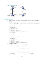
Figure 115
Network diagram
Configuration procedure
1.
Configure IPv4 and IPv6 addresses and subnet masks for interfaces on the switches. (Details not
shown.)
2.
Configure IS-IS on the switches to make sure Switch A, Switch B, Switch C, and Switch D can
communicate with each other at Layer 3 and dynamic route update can be implemented among
them with IS-IS. (Details not shown.)
3.
Configure IPv6 IS-IS MTR:
# Configure Switch A.
<SwitchA> system-view
[SwitchA] isis
[SwitchA-isis-1] cost-style wide
[SwitchA-isis-1] multiple-topology ipv6-unicast
# Configure Switch B.
<SwitchB> system-view
[SwitchB] isis
[SwitchB-isis-1] cost-style wide
[SwitchB-isis-1] multiple-topology ipv6-unicast
# Configure Switch D.
<SwitchD> system-view
[SwitchD] isis
[SwitchD-isis-1] cost-style wide
[SwitchD-isis-1] multiple-topology ipv6-unicast
4.
Verify the configuration:
# Display the IS-IS routing table of the IPv6 topology on Switch A.
[SwitchA-isis-1] display isis route ipv6
Route information for ISIS(1)
-----------------------------
ISIS(1) IPv6 Level-1 Forwarding Table
-------------------------------------
Destination: 12:: PrefixLen: 64
Flag : D/L/- Cost : 4
Loop0
44::1/128
Switch A
Switch B
Switch D
Switch C
36
5
4
3
Vlan-int12
12::1/64
Vlan-int12
12::2/64
Vlan-int11
11.1.1.1/24
Vlan-int11
11.1.1.2/24
Vlan-int14
14::1/64
Vlan-int14
14::2/64
Vlan-int13
22.1.1.1/24
Vlan-int13
22.1.1.2/24


