Chapter 3
Installing the System
Attaching the Rear Kick Plates
134
Attaching the Rear Kick Plates
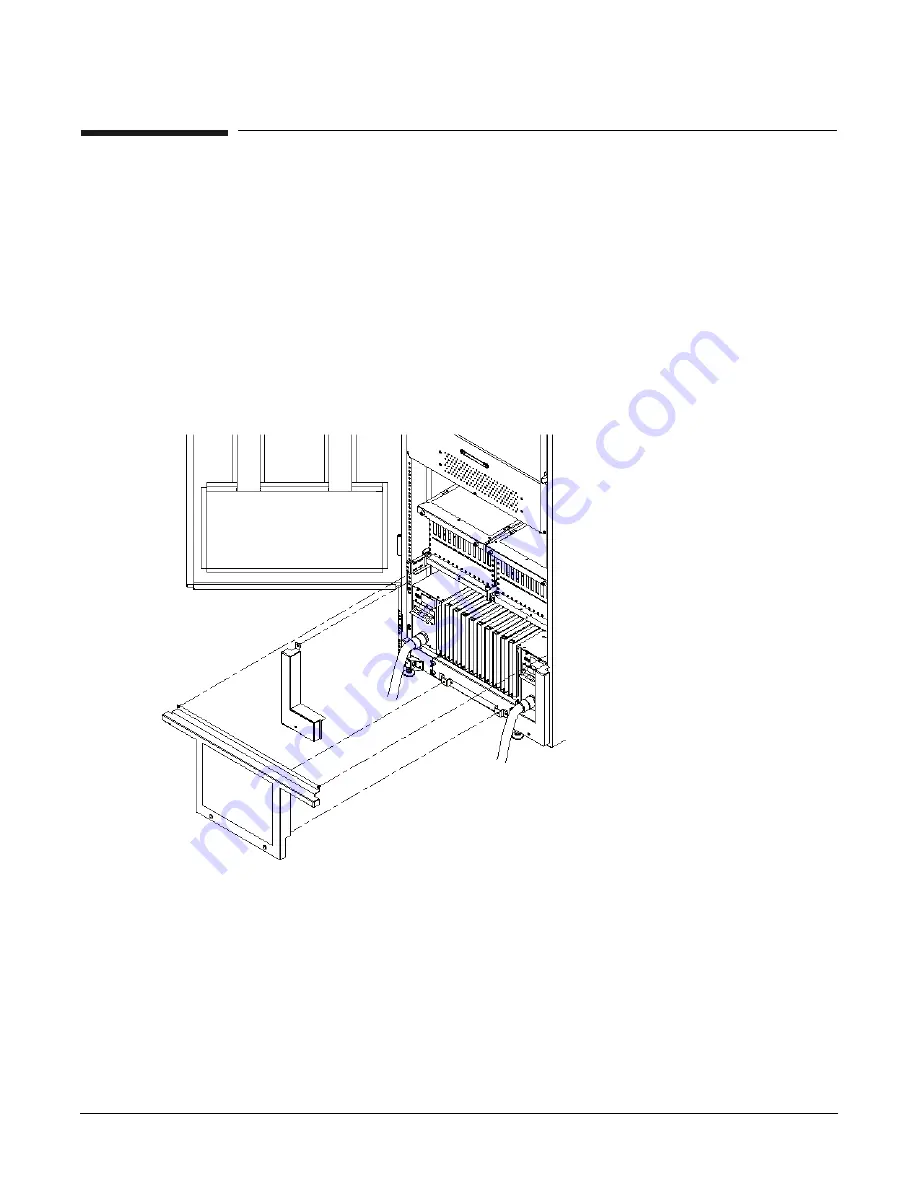
Kick plates protect cables from accidentally being disconnected or damaged and add an attractive cosmetic
touch to the cabinet. You need to attach three metal kick plates to the bottom rear of the cabinet.
To install the kick plates:
Step 1. Hold the left kick plate in position and attach a clip nut (0590-2318) on the cabinet column next to
the hole in the flange at the top of the kick plate (Figure 3-53).
Step 2. Using a screw (0515-0671) and a T-25 driver, attach the flange on the kick plate to the nut clip.
Step 3. Using a T-10 driver and a screw, attach the bottom of the kick plate to the center hole in the
leveling foot.
Figure 3-53 Attaching Rear Kick Plates
Step 4. Perform steps 1–3 on the right kick plate.
Step 5. Position the upper flange of the center kick plate under the I/O trays complementary mounting
bracket so as to retain the center kick plate top flanges. No top screws are needed on the center kick
plate due to this bracket. Orient this asymmetrical bracket with the hole located nearest the edge
in the up position.
Step 6. Using a T-20 driver, tighten the thumbscrews at the bottom of the center kick plate.
Содержание Integrity Superdome sx2000
Страница 8: ...Contents 8 ...
Страница 10: ...Tables 10 ...
Страница 14: ...Figures 14 ...
Страница 53: ...Chapter 1 Overview New Server Cabling 53 Figure 1 11 Backplane Cables ...
Страница 119: ...Chapter 3 Installing the System Turning On Housekeeping Power 119 Figure 3 37 BPS LEDs BPS LEDs ...
Страница 169: ...Appendix A 169 A sx2000 LEDs ...
Страница 174: ...Appendix A sx2000 LEDs 174 ...
Страница 187: ...Appendix B Management Processor Commands MP Command HE 187 Example B 11 HE Command ...
Страница 199: ...Appendix B Management Processor Commands MP Command PS 199 Example B 20 PS Command ...
Страница 212: ...Appendix B Management Processor Commands MP Command XD 212 ...
Страница 224: ...Appendix C Powering the System On and Off Turning On Housekeeping Power 224 Figure C 14 BPS LEDs BPS LEDs ...
Страница 230: ...Appendix D Templates Templates 230 Figure D 2 SD16 and SD32 Space Requirements ...
Страница 233: ...Appendix D Templates Templates 233 Figure D 4 Computer Floor Template ...
Страница 234: ...Appendix D Templates Templates 234 Figure D 5 Computer Floor Template ...
Страница 235: ...Appendix D Templates Templates 235 Figure D 6 Computer Floor Template ...
Страница 236: ...Appendix D Templates Templates 236 Figure D 7 Computer Floor Template ...
Страница 237: ...Appendix D Templates Templates 237 Figure D 8 Computer Floor Template ...
Страница 238: ...Appendix D Templates Templates 238 Figure D 9 SD32 and SD64 and I O Expansion Cabinet Templates ...
Страница 239: ...Appendix D Templates Templates 239 Figure D 10 SD32 and SD64 and I O Expansion Cabinet Templates ...
Страница 240: ...Appendix D Templates Templates 240 Figure D 11 SD32 and SD64 and I O Expansion Cabinet Templates ...
Страница 241: ...Appendix D Templates Templates 241 Figure D 12 SD32 and SD64 and I O Expansion Cabinet Templates ...
Страница 242: ...Appendix D Templates Templates 242 Figure D 13 SD32 and SD64 and I O Expansion Cabinet Templates ...
Страница 243: ...Appendix D Templates Templates 243 Figure D 14 SD32 and SD64 and I O Expansion Cabinet Templates ...
Страница 244: ...Appendix D Templates Templates 244 ...
Страница 247: ...Index 247 W wiring check 101 wrist strap usage 76 ...


