WLAN module
Description
Spare part number
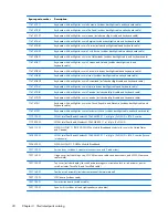
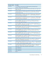
Intel Dual Band Wireless-AC 7260 802.11 ac (2x2) WiFi + BT 4.0 combo
710663-001
Intel Dual Band Wireless-N 7260AN 802.11 a/b/g/n (2x2) WiFi + BT 4.0 combo
717379-001
Intel Dual Band Wireless-N 7260NB 802.11 a/b/g/n (2x2) WiFi
717380-001
Intel Dual Band Wireless-N 7260AN 802.11 a/b/g/n (2x2) WiFi + BT 4.0 combo (for use in
Indonesia)
747833-001
CAUTION:
To prevent an unresponsive system, replace the wireless module only with a wireless
module authorized for use in the computer by the governmental agency that regulates wireless devices
in your country or region. If you replace the module and then receive a warning message, remove
the module to restore device functionality, and then contact technical support.
Before removing the WLAN module, follow these steps:
1.
Turn off the computer. If you are unsure whether the computer is off or in Hibernation, turn
the computer on, and then shut it down through the operating system.
2.
Disconnect the power from the computer by unplugging the power cord from the computer.
3.
Disconnect all external devices from the computer.
4.
Remove the battery (see
Battery on page 28
).
5.
Remove the service door (see
Service door on page 30
).
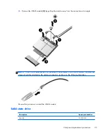
Remove the WLAN module:
1.
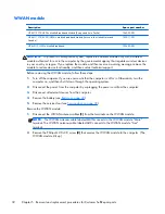
Disconnect the WLAN connector from the computer.
2.
Disconnect the WLAN antenna cables
(1)
from the terminals on the WLAN module.
NOTE:
The WLAN antenna cable labeled MAIN connects to the WLAN module “Main”
terminal. The WLAN antenna cable labeled AUX connects to the WLAN module “Aux” terminal.
3.
Remove the Phillips M2.0×2.5 screw
(2)
that secures the WLAN module to the system board.
(The WLAN module tilts up.)
34
Chapter 5 Removal and replacement procedures for Customer Self-Repair parts
Содержание EliteBook Revolve 810 G2 Tablet
Страница 1: ...HP EliteBook Revolve 810 G2 Maintenance and Service Guide ...
Страница 4: ...iv Important Notice about Customer Self Repair Parts ...
Страница 6: ...vi Safety warning notice ...
Страница 10: ...x ...
Страница 14: ...2 External component identification 4 Chapter 2 External component identification ...
Страница 24: ...Computer major components 14 Chapter 3 Illustrated parts catalog ...
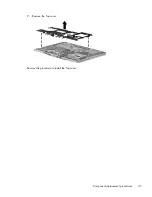
Страница 57: ...7 Remove the Top cover Reverse this procedure to install the Top cover Component replacement procedures 47 ...
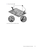
Страница 59: ...4 Remove the speakers 4 Reverse this procedure to install the speakers Component replacement procedures 49 ...

