


8
.
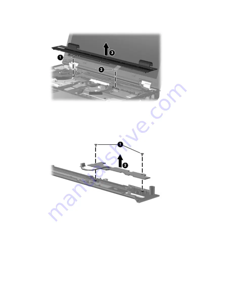
Remove the switch cover
(3)
by lifting it straight up until it disengages from the computer.
9
.
If it is necessary to replace the power button board, turn the switch cover upside down, with the
bottom of the switch cover toward you.
10
.
Remove the Phillips PM2.5×3.0 screw
(1)
that secures the power button board to the switch cover.
11
.
Remove the power button board
(2)
. The power button board is available using spare part number
446438-001.
Reverse this procedure to install the power button board and switch cover.
Component replacement procedures 65
Содержание Compaq 6910p
Страница 1: ...HP Compaq 6910p Notebook PC Maintenance and Service Guide ...
Страница 4: ...iv Safety warning notice ...
Страница 14: ...6 Chapter 1 Product description ...
Страница 24: ...16 Chapter 2 External component identification ...
Страница 26: ...Computer major components 18 Chapter 3 Illustrated parts catalog ...
Страница 98: ...90 Chapter 4 Removal and replacement procedures ...
Страница 122: ...Where used 2 screws that secure the system board to the base enclosure 114 Chapter 7 Screw listing ...
Страница 126: ...Where used 9 screws that secure the top cover to the computer 118 Chapter 7 Screw listing ...
Страница 136: ...128 Chapter 7 Screw listing ...
Страница 166: ...158 Index ...
Страница 167: ......
Страница 168: ......


