c.
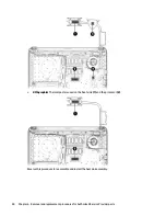
Remove the display bezel (4).
NOTE:
The following image shows the display panel connected to the computer. It will not be
connected in this procedure.
2.
To remove the webcam/microphone module:
a.
Position the display assembly with the top edge toward you.
b.
Lift to disengage the adhesive that secures the webcam/microphone module to the display, and
then remove the module (1) enough to disconnect the cable.
c.
Disconnect the cable (2) from the module.
3.
To remove the display panel:
a.
Remove the four Phillips PM2.0×3.0 screws that secure the display panel to the enclosure.
60
Chapter 6 Removal and replacement procedures for Authorized Service Provider parts
Содержание 340 G3
Страница 1: ...HP 340 G3 Notebook HP 346 G3 Notebook HP 348 G3 Notebook Maintenance and Service Guide ...
Страница 4: ...iv Safety warning notice ...
Страница 22: ...14 Chapter 2 External component identification ...
Страница 36: ...28 Chapter 5 Removal and replacement procedures for Customer Self Repair parts ...
Страница 54: ...46 Chapter 6 Removal and replacement procedures for Authorized Service Provider parts ...
Страница 88: ...80 Chapter 10 Backing up restoring and recovering in Windows 10 ...
Страница 106: ...98 Chapter 14 Power cord set requirements ...
Страница 108: ...100 Chapter 15 Recycling ...
Страница 112: ...104 Index ...


