background image

MAN0508-03 

08 JUN 2005 

PAGE 3 

b. DIN-Rail 

Mounting 

 
1. 

Read the Installation Chapter in the hardware manual of the controller you are using prior to 
mounting the FOX104 / FOX404.  Observe requirements for the panel layout design and 
adequate clearances.  A checklist is provided for your convenience in the hardware manual. (See 
the 

Additional References

 section in this document.) 

2. 

Determine length of DIN-Rail needed.  (Refer to Figure 2.) 
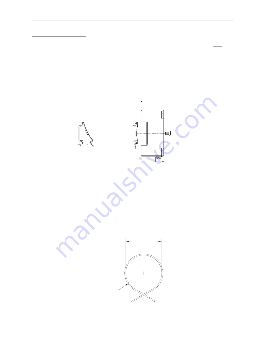
3. 

Noting the proper location, attach two (2) DIN-Rail mounting clips (included with FOX unit) to the 
DIN-Rail by hooking the clips over the top of the Rail and rocking down and snapping over the 
bottom of the Rail.  (Refer to Figure 3.) 

4. 

Adjust clips as necessary by sliding them along the DIN-Rail to align with the holes in the tabs of 
the FOX unit. Using the provided screws, mount the Fox unit to the clips. Tighten screws as 
necessary to hold the unit securely. (Refer to Figure 3.) 


Figure 3 – (Left) DIN-Rail and Mounting Clips, and (Right) FOX104 / FOX404 DIN-Rail Mounting


2.4 

Fiber Optic Cable Installation 

 
Important considerations for installing the FOX include the following guidelines:    
 
a. 

To ensure reliable communication between the FOX base and OCS/RCS module, high quality 
cables need to be installed.  See Table 2 for fiber cable part numbers.  

b. 

The maximum fiber optic cable distance is 10 meters between drops. 

c. 

During installment of the fiber optic cable, all direction changes need to adhere to a 

Minimum 

Bend Radius

 of one inch (25.44mm).  


Figure 3 – Fiber Optic Cable Bend Radius


1.00” (25.4mm) Min.

Bend Radius 

001FOX011

2.00” (50.8mm)

Min. Diameter 

001FOX012

Close-up of mounting clips 
being hooked on to DIN-rail. 

DIN-Rail 

Mounting 

Clips 

FOX104 / 
FOX404 

Содержание HE800FOX104

Страница 1: ... Draw 9 30VDC 400mA maximum Height 4 25 108 mm Width 6 63 168 3 mm Mounting Depth 4 7 119 4 mm Operating Temperature 32 122 F 0 50 C Humidity 5 to 95 non condensing UL Class I Groups A B C D Division 2 CE Yes 2 INSTALLATION 2 1 Mounting Orientation The base of the FOX104 FOX404 need to be mounted with the proper orientation Proper orientation helps to ensure a good connection when SmartStack Modul...

Страница 2: ... section in this document 2 Drill holes Refer to Figure 2 3 Install and tighten washers and nuts Do not over tighten 4 Connect the communications and power cables to the FOX104 FOX404 ports using the provided connectors 5 Install up to four SmartStack Modules on the FOX104 FOX404 2 3 Dimensions and Hole Pattern Figure 2 FOX104 404 Hole Pattern Top and Viewed with 4 SmartStack I O Modules Bottom NO...

Страница 3: ...th the holes in the tabs of the FOX unit Using the provided screws mount the Fox unit to the clips Tighten screws as necessary to hold the unit securely Refer to Figure 3 Figure 3 Left DIN Rail and Mounting Clips and Right FOX104 FOX404 DIN Rail Mounting 2 4 Fiber Optic Cable Installation Important considerations for installing the FOX include the following guidelines a To ensure reliable communic...

Страница 4: ...le 2 Fiber Optic Cables Feet Meters Part Number 3 3 ft 1 m HE800CBF001 6 6 ft 2 m HE800CBF002 16 4 ft 5 m HE800CBF005 32 8 ft 10 m HE800CBF010 Figure 5 FOX Power Connector Figure 6 FOX Power Connector PIN 1 PIN 2 PIN 3 PIN 1 PIN 2 PIN 3 IN 1 2 3 4 TO REMOTE BASE IN IN IN 001FOX004 Power Connection Host Fiber Optic Connection 24VDC FROM OCS HUB IN 001FOX003 R1 OUT ...

Страница 5: ... 1 0 1 5 FOX104 FOX404 LEDs Table 4 FOX104 FOX404 LEDs FIBER OK ON indicates FOX s fiber input cable is properly connected and is receiving a carrier PWR ON indicates FOX is receiving power RUN OFF indicates OCS is in IDLE STOP mode or no power to the FOX or one of the fiber cables are detached or there is a configuration mismatch Flashing indicates DO IO mode or RUN with no ladder program ON indi...

Страница 6: ...te The following examples depict the FOX100 but they also apply to the FOX110 Figure 9 OCS RCS to FOX404 Single Hub via FOX100 001OCS010 R2 4 3 2 1 HOST Color Touch OCS Or Or Using FOX100 RCS250 Using FOX100 OCS110 OCS210 Graphic OCS OCS250 HUB FOX404 ...

Страница 7: ...ure 10 OCS RCS to FOX One Hub FOX404 and Multiple Bases FOX104 via FOX100 HOST 4 3 2 1 HOST HOST 001OCS012 R2 HOST Color Touch OCS Or Or Using FOX100 RCS250 Using FOX100 OCS110 OCS210 Graphic OCS OCS250 HUB FOX404 FOX104 FOX104 FOX104 ...

Страница 8: ... RCS to FOX Multiple Hubs FOX404 and Bases FOX104 via FOX100 HOST HOST 4 3 2 1 HOST HOST 001OCS011 R2 HOST 4 3 2 1 Color Touch OCS Or Or Using FOX100 RCS250 Using FOX100 OCS110 OCS210 Graphic OCS OCS250 HUB FOX404 HUB FOX404 FOX104 FOX104 FOX104 ...

Страница 9: ...loor are dry before making any connection to a power line Make sure the unit is turned OFF before making connection to terminals Make sure all circuits are de energized before making connections Before each use inspect all cables for breaks or cracks in the insulation Replace immediately if defective Warning Consult user documentation Warning Electrical Shock Hazard WARNING To avoid the risk of el...

Страница 10: ...OCS OCX e g OCS1XX 2XX Graphic OCS250 Remote Control Station Hardware RCS except RCS116 RCX e g RCS210 RCS250 MAN0227 Color Touch OCS Hardware e g OCS300 OCS301 OCS350 OCS351 e g OCS451 OCS551 OCS651 MAN0465 OCS LX Series Hardware e g LX280 LX300 RCS116 MAN0755 MiniOCS MiniRCS MiniOCX MiniRCX Hardware e g HE500OCSxxx MAN0305 Other Useful References Cscape Programming and Reference MAN0313 DeviceNe...

Отзывы: