


SYSTEM DESCRIPTION, INSTALLATION, AND MAINTENANCE MANUAL
MCS--4200/7200 Multi--Channel SATCOM System
23--20--35
15 Jul 2006
Honeywell International Inc. Do not copy without express permission of Honeywell.
Page 5--73
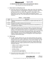
Table 5-37.
Per Channel State Definition (MP11F=0)
CD1
CD2
Channel State
High
1
High
On Hook
Low
1
High
Call Initiated/Connected
2
High
Low
Call Answered
Low
Low
Incoming Call
NOTES:
1.
“High” and “Low” (impedance -- -- open--collector--type output) are as defined in ARINC 741 Part 1 Attachment 1--4
Note 10.
2.
Depending on the state of SDU system configuration pin TP10K, the state will transition on either call initiation or
call connection.
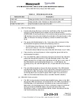
Z.
Strap Parity
(1) The interpretation of this configuration pin is given in Table 5-38.
Table 5-38.
Strap Parity
MP11 Pin E
Interpretation
0
SUM OF ALL STRAPS IS SET TO EVEN
1
SUM OF ALL STRAPS IS SET TO ODD
(2) This pin is set to the zero or one state to yield an even number of strapped pins
(MP11E to MP11K).


