SYSTEM DESCRIPTION, INSTALLATION, AND MAINTENANCE MANUAL
MCS--4200/7200 Multi--Channel SATCOM System
23--20--35
15 Jul 2006
Honeywell International Inc. Do not copy without express permission of Honeywell.
Page 6--49
(f)
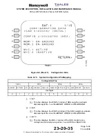
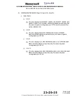
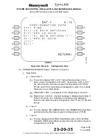
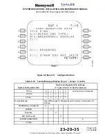
CONFIGURATION DATA Page 5 (Figure 6-8, sheet 5):
1
Data Fields
a
Line 4
(1) This line displays A(0) PARITY: GOOD, A(1) PARITY: GOOD, A(0)
PARITY: BAD, or A(1) PARITY: BAD left-justified as determined by
the state of system configuration pin TP11A and the result of the
parity validation test.
b
Line 6
(1) This line displays B(0) CCS INSTALLED or B(1) CCS NOT
INSTALLED left-justified as determined by the state of system
configuration pin TP11B.
c
Line 8
(1) This line displays C(0) PRI IRS INSTALLED or C(1) PRI IRS NOT
INSTLLD left-justified as determined by the state of system
configuration pin TP11C.
d
Line 10
(1) This line displays D(0) SEC IRS INSTALLED or D(1) SEC IRS NOT
INSTLLD left-justified as determined by the state of system
configuration pin TP11D.


