


SYSTEM DESCRIPTION, INSTALLATION, AND MAINTENANCE MANUAL
MCS--4200/7200 Multi--Channel SATCOM System
23--20--35
15 Jul 2006
Honeywell International Inc. Do not copy without express permission of Honeywell.
Page 6--54
(i)
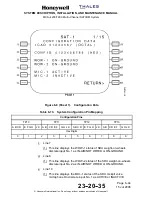
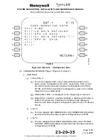
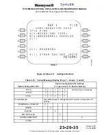
CONFIGURATION DATA Page 8 (Figure 6-8, sheet 8):
1
Data Fields
a
Line 4
(1) This line displays F(0) THIS IS SDU2 or F(1) THIS IS SDU1
left-justified as determined by the state of system configuration pin
TP12F.
b
Line 6 --
(1) This line displays G(0) CMU1 INSTALLED or G(1) CMU1 NOT
INSTALLED left-justified as determined by the state of system
configuration pin TP12G.
c
Line 8
(1) This line displays H(0) CMU2 INSTALLED or H(1) CMU2 NOT
INSTALLED left-justified as determined by the state of system
configuration pin TP12H.
d
Line 10
(1) This line displays J(0) SCDU1 INSTALLED or J(1) SCDU1 NOT
INSTALLED left-justified as determined by the state of system
configuration pin TP12J.
e
Line 12
(1) This line displays K(0) SCDU2 INSTALLED or K(1) SCDU2 NOT
INSTALLED left-justified as determined by the state of system
configuration pin TP12K.


