background image

T775U SERIES 2000 ELECTRONIC STAND-ALONE CONTROLLER

21

62-0255—07

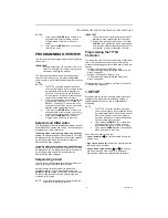
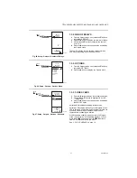
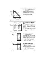
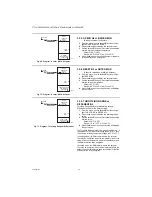
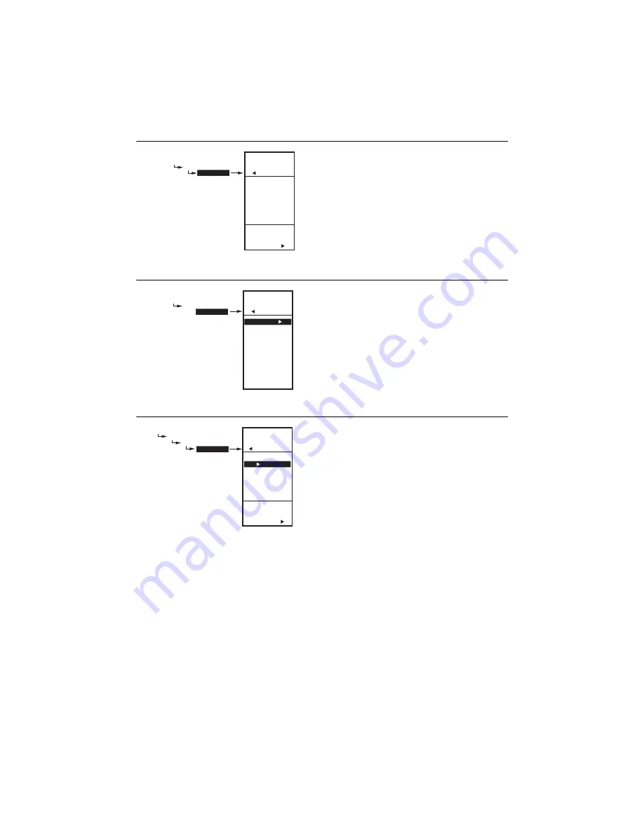
Fig. 45. Setup - Outputs - Number of Relays.

1.3.2. NBR OF RELAYS 

1.

From the Outputs menu, use the 

S

and 

T

 buttons 

to highlight # RELAYS.

2.

Press the 

X

 button to display the number of relays.

3.

Use the 

S

 and 

T

 buttons to display the number 

from 1 to 2.

4.

Press the 

X

 button to accept the value and display 

the Outputs menu.

The number of relay outputs entered here determines 
how many relays display on the home screen.

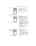
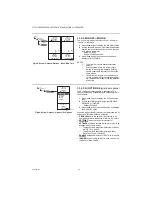
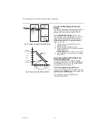
Fig. 46. Setup - Outputs - Options Menu.

1.3.3. OPTIONS

1.

From the Outputs menu, use the 

S

and 

T

 buttons 

to highlight OPTIONS. 

2.

Press the 

X

 button to display the Options menu.

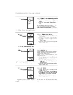
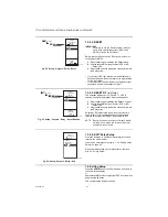
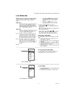
Fig. 47. Setup - Outputs - Options - Schedule.

1.3.3.1. USE SCHED 

1.

Press the 

X

 button to display the schedule selections.

2.

Use the 

S

and 

T

 buttons to highlight YES or NO.

Default: NO

3.

Press the 

X

 button to accept the value and display 

the MIN OFF option.

Selecting NO disables scheduling for 

all

 outputs.

Selecting YES enables scheduling for 

all

 outputs. When 

YES is selected, all individual outputs default to follow the 
schedule. However, each individual output can be 
removed from scheduling as desired. 
With Scheduling enabled, when you return to Program 
mode, the new option for Scheduling displays. You can 
press the 

HOME

 button and then the 

MENU

 button to 

view the Schedule options in the menu.
See “1.3.1.5. SCHEDULE” on page 19.

SETUP


OUTPUTS

  # 

RELAYS

ENTER

NUMBER OF 

RELAYS

SETUP

OUTPUTS

# RELAYS

2

M24607

SETUP
  

OUTPUTS

  OPTIONS

SETUP

OUTPUTS

OPTIONS

USE SCHED

MIN OFF

MIN ON

DI OPTS

SHOW RT

EXIT

M24608A

SETUP
 OUTPUTS


OPTIONS


USE SCHED

SETUP

OUTPUTS

OPTIONS

USE SCHED

USE

SCHEDULE

FOR

OUTPUTS

YES

NO

M24609

Содержание T775U Series

Страница 1: ...ng safety or limit controls a separate safety or limit control device is required Table 1 T775U Controller Configurations Controller Modela a The T775U includes a digital input for use with the disable or setback option Description Replaces Output Reset SPDT Relay Outputs Analog Mod Outputsb b The modulating analog outputs may be 4 20 mA 0 10 Vdc 2 10 Vdc or Series 90 selectable Sensor Inputs Nbr ...

Страница 2: ...sors and is settable in PPM units Universal Sensors Sensor A only The controller accepts 0 5 Vdc 0 10 Vdc or 4 20 mA input for temperature pressure humidity CO2 etc They may be programmed in units of F C Pa kPa PSI In W C PPM or may be unitless none The PPM range is 0 to 9990 Choosing none for units results in no units being displayed on the home screen If no unit is specified the range is 9999 to...

Страница 3: ...terface and Programming overview see page 11 5 Setup see page 13 6 Programming the Controller with no Reset see page 25 or Programming the Controller with Reset page 28 7 Scheduling optional see page 33 Additional topics are Sensor calibration begins on page 10 Interface overview begins on page 11 Summary menu begins on page 37 Troubleshooting begins on page 37 MOUNTING This section describes the ...

Страница 4: ...e electrical codes and ordinances or as specified on installation wiring diagrams Controller wiring is terminated to the screw terminal blocks located inside the device The remainder of this section describes the sensor wiring and the T775U controller wiring Wiring Connections Access To access the wiring connections remove the two screws on the left side of the enclosure and gently swing open the ...

Страница 5: ...ommended The sensors in Fig 5 8 beginning on page 6 are examples and illustrate voltage and current wiring for 3 wire and 2 wire sensors to the Sensor A terminal For terminal wiring details see Fig 11 and Table 2 on page 8 Other sensors are supported See sensor descriptions on page 2 NOTES 1 Other transmitters can be wired in the same manner For example the 0 10Vdc wiring shown in Fig 5 on page 6 ...

Страница 6: ...DITY SENSOR 0 10 VDC CONNECTION SENSOR A 1 SENSOR B C S V T T VO GND VIN C S V SHIELDED CABLE M24890C V S SHIELDED CABLE MUST BE CONNECTED TO A SEPARATE EARTH GROUND DO NOT GROUND SHIELDED CABLE AT SENSOR END TO MINIMIZE NOISE PICKUP MAKE SENSOR CONNECTION FROM SHIELDED CABLE AS CLOSE AS POSSIBLE TO SENSOR BODY THE T775 HAS AN INTEGRAL LOAD OF 500 OHMS WHICH RESULTS IN A 10V DROP AT 20MA TO USE 4 ...

Страница 7: ...d low voltage wiring Knockouts C D and E can be used to gain access to the load relay output terminals and 120 240 Vac power wiring Controller Wiring Method Wire the sensors and outputs then wire the power connection Each terminal can accommodate the following gauges of wire Single wire from 14 AWG to 22 AWG solid or stranded Multiple wires up to two 22 AWG stranded For 24 120 or 240 Vac power con...

Страница 8: ...V 4 20mA input see Fig 7 on page 6 24 Vac Power T T Temperature Sensor polarity insensitive 24V 24 Vac Hot Common 24 Vac Common Sensor B T T Temperature Sensor polarity insensitive Ground Earth Groundc c A separate earth ground is required for all installations regardless of the power source 24 120 or 240 Vac 120 or 240 Vac Power Input 120 Vac 120 120 Vac Power DI Digital Input dry contact Common ...

Страница 9: ... Fig 15 Wiring for Digital Input dry contact Fig 16 Wiring for mod motor or direct coupled actuator with 0 10 Vdc control input L1 HOT L2 24 VAC COM NO COM NO M24554A C S V T T LOAD 2 LOAD 1 C NO NC C NO NC C FOR SPECIFIC SENSOR WIRING TEMPERATURE HUMIDITY PRESSURE ETC REFER TO THE SENSOR WIRING SECTIONS BEGINNING ON PAGE 4 1 1 USE SEPARATE TRANSFORMER FOR T775 WHEN USING 24 VAC 1 M24557A MODULATI...

Страница 10: ...ue by the amount shown in the Table 4 on page 11 For example a wire run with 18 gauge wire of 1 000 feet requires a calibration offset of 6 0 F IMPORTANT If the calibration value in the table exceeds the controller s calibration limits of 10 F 6 C you must use a heavier gauge wire For example with a wire run of 1 000 feet you must use 20 AWG wire or heavier in order to cal ibrate for wire loss wit...

Страница 11: ...ugh the menus and enter or change parameter values Home Button Pressing the HOME button at any time exits the current Programming or Setup display screen and returns to the home screen as shown in Fig 20 and Fig 21 Menu Button Pressing the MENU button always displays the Program menu If you are in Setup mode you exit setup and return to the Program menu Pressing and holding the MENU button for fiv...

Страница 12: ...e screen displays the effective setpoint IMPORTANT After four minutes of inactivity no buttons pressed the LCD display reverts to the home screen display Accessing the Menus Menus are used for programming scheduling viewing the summary settings and setup of advanced options Program Schedule and Summary Menus To access these menus from the home screen press the MENU button See Fig 22 Fig 22 Menus D...

Страница 13: ...ay energizes Setpoint High Limit You can set an irreversible setpoint high limit maximum value for any single displayed setpoint value Adjust the setpoint at any output to the desired maximum setpoint Then simultaneously press the HOME W and X buttons and continue to press all three buttons for five seconds to set the setpoint high limit maximum to this value NOTE You must press all three buttons ...

Страница 14: ...NSORS The value entered here determines the number of sensors displayed on the home screen NOTE For applications that do not use Reset only one sensor Sensor A is available for use 1 From the Sensors menu highlight SENSORS then press the X button to display the number of sensors 2 Use the S and T buttons to enter the number of sensors 1 or 2 Default 2 3 Press the X button to accept the value and d...

Страница 15: ... A 1 From the Sensor A selections use the S and T buttons to highlight UNITS 2 Press the X button to display the temperature units 3 Use the S and T buttons to highlight F or C Default F Fahrenheit 4 Press the X button to accept the units and return to the Sensor A selections Continue with 1 2 2 3 CALIBRATE Sensor A or B Fig 29 Setup Sensors Sensor A Units 1 2 2 2 2 UNITS Sensor A only 0 5V 0 10V ...

Страница 16: ...e 3 Use the S and T buttons to increase decrease the desired calibration value Default 0 0 Sensor Range Temperature 10 F 6 C Other Sensor Range 10 of the Min to Max values specified previously See Table 3 on page 10 for examples 4 Press the X button to accept the value and return to the Sensor A selections Fig 32 Setup Sensors Sensor A Label 1 2 2 4 LABEL Sensor A or B input For a sensor already l...

Страница 17: ...through 1 2 2 4 LABEL Sensor A or B input beginning on page 14 but perform only those steps applicable to Sensor B 4 Press the W button to exit SENSOR B and return to the Sensors menu or Use the S and T buttons to highlight EXIT and press the X button 5 Press the W button to exit the Sensors menu and return to the Setup menu Continue with 1 3 Setting up the Outputs Fig 35 Setup Outputs Menu 1 3 Se...

Страница 18: ...ion Using the time clock or digital input to disable the output forces the output to 0 1 From the Mod menu use the S and T buttons to highlight MIN OUT 2 Press the X button to display the Min Out 3 Use the S and T buttons to increase decrease the desired value from 0 to 100 in 1 increments Default 0 Range 0 to 100 4 Press the X button to accept the percentage and return to the Mod menu Fig 39 Setu...

Страница 19: ...lling to a setpoint even with a wide throttling range Fig 40 Setup Outputs Mod Out Derivative 1 3 1 4 DERIVATIVE The Derivative default value is factory set to zero no derivative control It is strongly recommended that the derivative remain at zero 0 unless you have a very good reason to adjust it Derivative control is not needed in the vast majority of HVAC applications 1 From the Mod menu use th...

Страница 20: ...od 1 2 Hide 1 3 1 7 Hide The Hide option is used to prevent the MOD 1 and MOD 2 outputs from displaying on the Home screen 1 From the Mod menu use the S and T buttons to highlight HIDE 2 Use the S and T buttons to highlight YES or NO Default YES 3 Press the X button to accept the selection and return to the MOD menu NOTE The MOD1 and MOD2 outputs are still active even when hidden from the Home scr...

Страница 21: ...n to display the schedule selections 2 Use the Sand T buttons to highlight YES or NO Default NO 3 Press the X button to accept the value and display the MIN OFF option Selecting NO disables scheduling for all outputs Selecting YES enables scheduling for all outputs When YES is selected all individual outputs default to follow the schedule However each individual output can be removed from scheduli...

Страница 22: ...y Setpoint Setback values entered in the Schedule 1 Press the X button to display the DI Option selec tions 2 Use the S and T buttons to highlight DISABLE SETBACK or IGNORE Default DISABLE 3 Press the X button to accept the value and display the SHOW RT option When the digital input DI closes all outputs follow the DI option value Disable Setback or Ignore DISABLE disables the outputs relays retur...

Страница 23: ...e the S and T buttons to highlight the desired relay 1 or 2 2 Press the X button to display the selected Relay menu Continue with the remainder of this section to setup the relay outputs Fig 53 Setup Outputs Relay Schedule 1 3 4 1 SCHEDULE This selection displays only if Use Sched YES is selected during the Output Options setup see page 21 When selected individual outputs default to follow the sch...

Страница 24: ...uttons to select YES or NO Default NO 3 Press the X button to accept the value and return to the Relay menu Selecting YES immediately resets the output run time hours to zero for this output When you subsequently return to this screen the RESET RT defaults to NO NOTE Run times can be reset to zero for each individ ual relay You must do this for each relay that you want to reset to zero Fig 56 Setu...

Страница 25: ...for selecting MOD 1 but other than as noted below the programming is the same for each output NOTE For Relays DIFFRNTL replaces THROT RNG NOTE The Setback parameter displays only if schedul ing is enabled see Fig 47 on page 21 or the DI Option is set to Setback see Fig 49 on page 22 Continue with 2 1 2 SETPOINT Fig 59 Program Setpoint 2 1 2 SETPOINT 1 From the menu use the S and T buttons to high ...

Страница 26: ... Throttling Range displays for Modulating outputs Differential is used for the Relay outputs 1 From the menu use the S and T buttons to high light THROT RNG or DIFFERNTL 2 Press the X button to display the throttling range value 3 Use the S and T buttons to increase decrease the desired value Default 20 F 6 6 C Range 1 F to 150 F 1 C to 66 C 4 Press the X button to accept the value and display the...

Страница 27: ...t Output Modulating Output or Relay For the next output select the desired MOD or Relay from the Program menu see Fig 57 on page 25 Go to 2 1 2 SETPOINT on page 25 to continue programming When you finish programming the outputs continue with 1 3 Exit Programming without Reset 1 3 Exit Programming without Reset Press the HOME button to leave programming mode and return to the home screen This compl...

Страница 28: ... the controlled temperature e g Boiler Sensor B must be sensing the resetting temperature e g outdoor temp To program an output for Reset refer to the values as shown in the examples below Choose your own appropriate values for Sensor A maximum and minimum and Sensor B maximum and minimum Reset Example see Fig 65 Sensor A is the boiler sensor and Sensor B is the outdoor sensor Maximum boiler tempe...

Страница 29: ...A1 2 Press the X button to display the maximum setpoint value 3 Use the S and T buttons to increase decrease the desired maximum setpoint temperature Default 180 F 82 C Range 40 F to 248 F 40 C to 120 C 4 Press the X button to accept the setpoint tempera ture and display the next option Fig 68 Program Sensor B Max Setpoint 3 2 2 RESET B1 or OUTSD MIN Sensor B value when at SP MAX A1 Setpoint 1 Fro...

Страница 30: ...tputs Differential is used for the Relay outputs 1 From the menu use the S and T buttons to high light THROT RNG or DIFFERNTL 2 Press the X button to display the throttling range value 3 Use the S and T buttons to increase decrease the desired value Default 20 F 6 6 C Range 1 F to 150 F 1 C to 66 C 4 Press the X button to accept the value and display the next option The Throttling Range brackets t...

Страница 31: ... see Fig 49 on page 22 This value is the number of degrees plus or minus that you want the temperature to be offset from the setpoint For example If you want the temperature to be 10 F less than the setpoint during setback mode enter 10 F In normal operations for heating the offset will be negative For cooling the offset will be a positive value 1 From the menu use the S and T buttons to high ligh...

Страница 32: ...re OFFSET Default 0 F OFFSET Range 150 F to 150 F 101 C to 66 C 4 Press the X button to accept the value and display the next option 3 3 2 Second Modulating Output and Relays Programming To complete the programming of MOD 2 or a Relay perform the procedures in 3 2 5 THROTTLING RANGE or DIFFERENTIAL through 3 2 7 SETBACK OFFSET if configured beginning on page 30 3 4 Exit Programming with Reset When...

Страница 33: ... to the home screen 2 If you press the MENU button you exit Scheduling mode and return to the menu To create or change a schedule you use the Left arrow button W to scroll backward through the Setup menus Right arrow button X to select the highlighted menu item and display its content Up and Down arrow buttons S and T to scroll up and down through a list of items or to increase or decrease the val...

Страница 34: ...e the S and T buttons to highlight SET DATE 2 Press the X button to display the current system date setting 3 Use the X button to cycle between the month day and year values 4 Use the S and T buttons to increase decrease the desired value for the month day and year 5 Press the W button to accept the Date and return to the Options menu Fig 80 Schedule Options Daylight Saving Time 4 2 3 DAYLIGHT day...

Страница 35: ...1 E1 SETPT setpoint for event 1 The following figures show the MON FRI menu but the menu selections are the same for any time period Fig 82 Schedule Event 1 Setpoint 4 3 1 E1 SETPT setpoint for event 1 1 From the selected time period menu use the S and T buttons to highlight E1 SETPT 2 Press the X button to display the setpoint options 3 Use the S and T buttons to highlight the desired option 4 Pr...

Страница 36: ... 35 above 4 3 4 E2 TIME time for event 2 Creating the time for event 2 is accomplished the same way as the first event See 4 3 2 E1 TIME time for event 1 above 4 3 5 EXIT exit from selected time period settings After entering the time for event 2 use the W button to exit the schedule time period and return to the Schedule menu to select a different time period When you finish scheduling the time p...

Страница 37: ...the same as written into the EEPROM This error cannot be field repaired Replace the device Diagnostic Messages There are two diagnostic messages that can display in response to sensor problems The diagnostic codes that can flash on the display are Sensor Open or Shorted Two dashes display when a sensor typically temperature is open or shorted An open circuit is considered anything greater than 157...

Страница 38: ...rence to radio communications However there is no guarantee that interference will not occur in a particular installation If this equipment does cause interference to radio or television equipment reception which can be determined by turning the equipment off and on the user is encouraged to try to correct the interference by one or more of the following measures Reorient or relocate the receiving...

Страница 39: ...T775U SERIES 2000 CONTROLLER 39 62 0255 07 ...

Страница 40: ...tions Honeywell International Inc 1985 Douglas Drive North Golden Valley MN 55422 Honeywell Limited Honeywell Limitée 35 Dynamic Drive Toronto Ontario M1V 4Z9 customer honeywell com U S Registered Trademark 2009 Honeywell International Inc 62 0255 07 E K Rev 10 09 Printed in U S A ...

Отзывы: