


R4140G, L AND M FLAME SAFEGUARD PROGRAMMING CONTROLS
60-0770—2
12
쐉
All limits and interlocks are reset.
씈
If you are installing a TRADELINE® model or an
international model (rated for other than 120V, 60 Hz)
check for one (or both) of these special features.
a.
If the R4140 has provisions for extending the
main burner flame-establishing period (MBFEP)
at terminal 6, make sure the jumper is, or is not,
installed on the back of the programmer,
depending on the MBFEP desired.
W136A
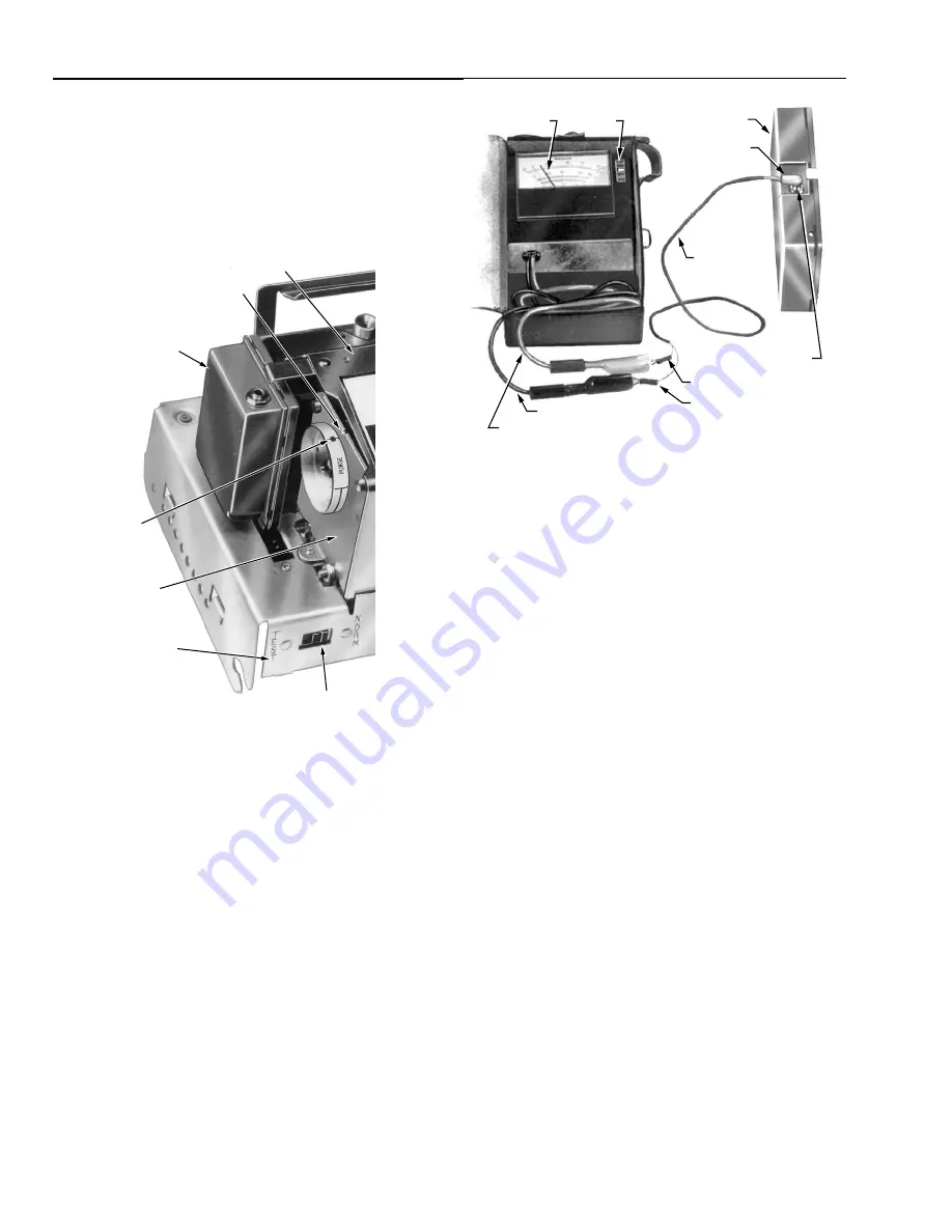
TEST METER
SELECTOR
SWITCH
PLUG IN FLAME
SIGNAL AMPLIFIER
196146 METER
CONNECTOR
PLUG
RED (+) METER LEAD
BLACK (-) METER LEAD
FLAME SIGNAL
METER JACK
RED SPADE TIP
BLACK SPADE TIP
PLUG
M6424
Fig. 10. Measuring the flame signal.
���
Read the average stable current. For an R7247B or C
or an R7476A Dynamic Self-Check Amplifier, disregard
the peaks due to self-checking operation. The red
flame-indicating lamp on a self-checking amplifier
should blink:
—
about 2-1/2 to 4 times a second on an R7247B.
—
about 1 to 2 times a second on an R7247C or
R7476A.
—
at the same rate that the flame is flickering (can
be as high as 20 times a second) on an R7248B.
If the lamp is on or off continuously while reading the flame
signal, replace the amplifier.
���
The meter reading must be as specified in Table 4 after
all tests are complete and all adjustments are made.
If the signal is unstable or less than the minimum acceptable
current, check the flame detector installation and circuitry.
���
Check the supply voltage at terminals L1-L2 on the
wiring subbase. Make sure the master switch is closed,
connections are correct, and the power supply is of the
correct voltage and frequency.
���
Check the detector wiring for defects including:
—
incorrect connections.
—
wrong type or size of wire.
—
deteriorated wire.
—
open circuits.
—
short circuits.
—
leakage paths caused by moisture, soot, or
accumulated dirt.
���
For a flame rod, make sure:
—
there is enough ground area.
—
the flame rod is properly located in the flame.
—
temperature at the flame rod insulator is no
greater than 500
°
F (260
°
C).
—
ignition interference is not present (see Ignition
Interference Test section).
RELAY/TIMER
COVER
INDEX NOTCH
PLUG-IN
AMPLIFIER
BOTTOM OF
PROGRAMMER
CHASSIS
TIMER SWITCH
TIMER
DOT ON
TIMER DIAL
M7966
Fig. 9. Location of timer switch and position of timer dial
at startup.
Flame Signal Measurement (Fig. 10 and
Table 4) for All Installations
Measure the flame signal at the appropriate times defined in the
following checkout tests. Read the flame signal in microamps at
the meter jack on the plug-in flame signal amplifier.
���
Use a Honeywell W136A Test Meter. (If a W136A is not
available, a microammeter with a 0 to 25 uA dc range
can be used.)
���
Set the selector switch on the test meter to:
— 25 uA for all standard amplifiers (R7247A, R7248A,
and R7249A) or for an R7248B Dynamic Ampli-
Check® Infrared Amplifier or
— SPL for an R7247B or C or an R7476A Dynamic
Self-Check Amplifier. (If the test meter is not a
W136A, shunt the 0 to 25 uA dc range with a
50 microfarad capacitor.)
���
Use a part no. 196146 Meter Connector Plug, ordered
separately. Connect the red spade tip to the red (+)
meter lead and the black spade tip to the black (-)
meter lead.
���
Insert the plug into the flame signal meter jack and
allow a few seconds for the meter reading to stabilize.