
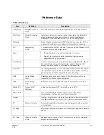


Reference Data
Release 3
34-ST-25-20 MC Toolkit User Manual
85
9/06
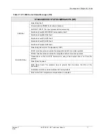
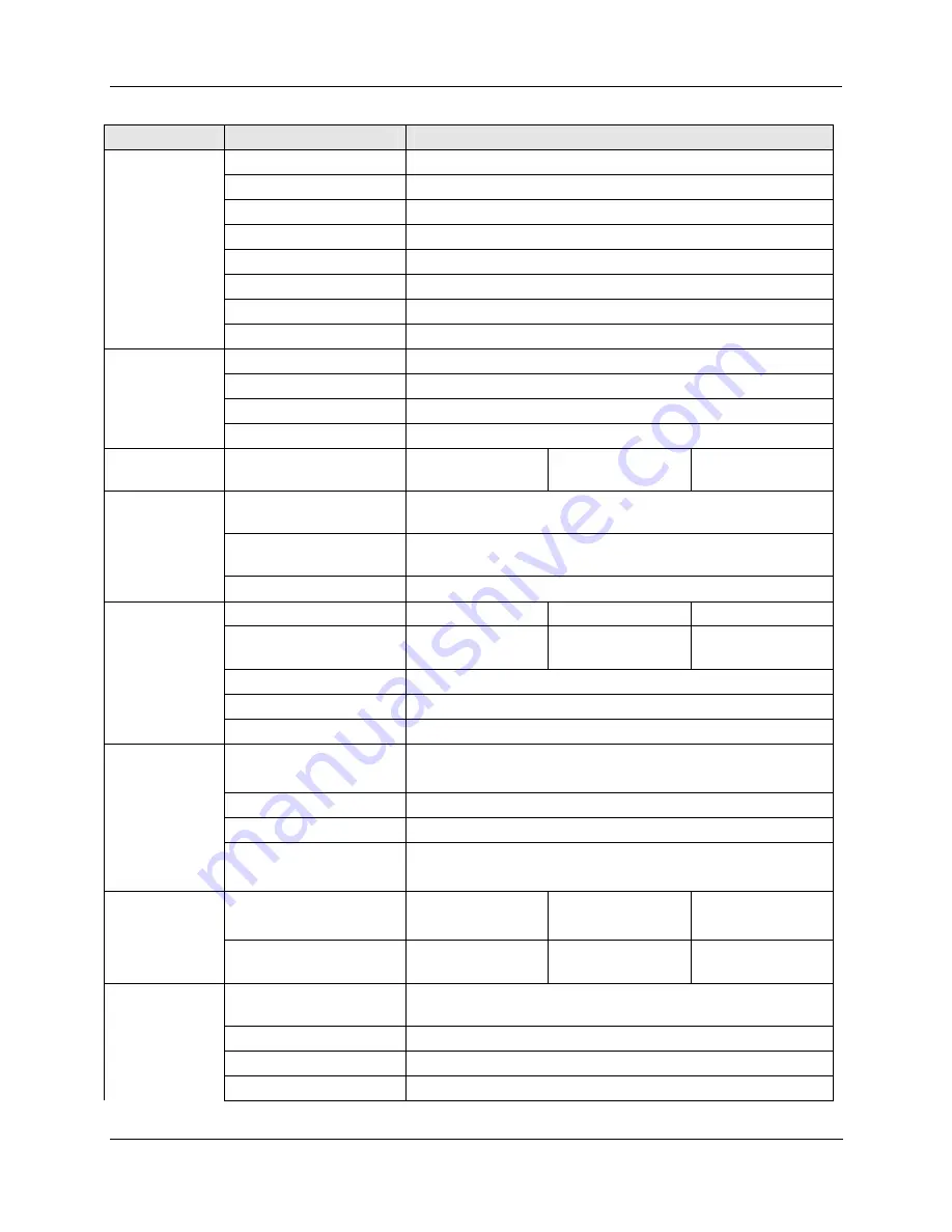
Dialog
Field
Value
Monitor Output
(mA)
Floating
point
Output
(%) Floating
point
PV
Floating
point
SV
Floating
point
TV
Floating
point
QV
Floating
point
Comm.
Status
String
value
Device Status
Displays the Device Status screen
Calibration
Zero Trim
Performs a Zero Trim
Apply Values
Displays the Apply Values screen
Loop Test
Displays the Loop Test screen
D/A Trim
Displays the D/A Trim screen
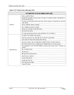
Apply Values,
screen 1
Set the (output current to)
4 mA
20 mA
Apply Values,
screen 2
Current Applied Process
Value
Floating point
Set As New Value
Sets the LRV or URV equal to the value in the Current Applied
Process Value edit box.
Read New Value
Updates the Current Applied Process Value edit box
Loop Test
Mode
Normal
Output Mode
Choose Analog Output
Level
4 mA
20 mA
Other
Other
Floating
point
Set Output
Sets the device output
Clear Output
Clears the Output Mode
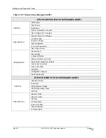
D/A Trim
Field Device Will Be
Scaled From
Floating Point
Change
Scale
Activates
the
2 edit boxes mentioned above.
Start D/A Trim
Starts the D/A Trim process
Meter Value
Floating point
Burst Mode
Burst Mode
Off
On
Not Used
None
Unknown
Special
Burst
Options
PV % Range and
Current
All PVs and
Current
Specific
Monitor
Number of Device
Variables to Query
1 - 4
Dev. Var. 1
0 - 22
Dev. Var. 2
0 - 22
Dev. Var. 3
0 - 22