


MC Toolkit Software with Honeywell HART Transmitters
Release 3
34-ST-25-20 MC Toolkit User Manual
39
9/06
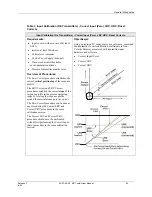
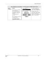
Table 8 HART Displays / Tasks Summary
Menu Item
Task
DEVICE INFO
Enter:
Device Type:
•
Tag ID
•
Message
•
Descriptor
Observe (Read):
•
Model
•
Device ID
•
Manufacturer
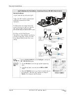
BASIC SETUP
Enter:
•
LRV
•
URV
Select:
•
Damping
•
PV Sensor Units (ST 3000,
STT25H, Generic
•
PV1 & PV2 Units(STT25T)
•
SV units (ST 3000)
•
Transfer Function (ST 3000,
Generic)
•
CJT Units (STT25H, STT25T)
•
PV Units Type (Generic)
Observe (Read):
•
LRL
•
URL
•
Sensor Type (ST 3000)
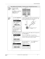
OUTPUT
CONDITION
Select:
•
Poll Adrs (0-15)
•
Scaled D/A Trim (Output
Calibration procedure)
•
NAMUR (STT 3000)
Observe (Read):
•
PV Output
•
PV2 (STT25T)
•
Alarm Direction
•
Requested Preambles
ALARM (STT 3000)
Select:
•
Break Detect (STT25H)
•
Latching Alarm
•
Clear Latching
•
XS Delta Detection (STT25T
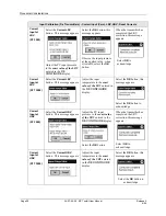
DIAGNOSTICS
/SERVICE
Select (Procedure):
•
Master Reset
•
Device Status
•
Monitor (Output: mA, %; PV, PV2
[STT25T}, SV)
•
Write Protect (Enter/Change
Password) (STT25H)
CALIBRATION
Select (Procedure):
Input Calibration
•
Zero Trim (ST 3000 and Generic)
•
Correct Input LRV (ST3000 and
STT25H)
•
Correct Input URV (ST3000 and
STT25H)
•
Reset Corrects (ST3000 and
STT25H)
Output Calibration
•
Loop Test
•
D/A Trim
Input (Re-Range to PV)
•
Apply Values (LRV, URV)