background image


7. 

Once Windows™ has detected the USB device, click 

NEXT

8. 

Now connect the RS-485 cable to the converter’s DB-9 terminal. 

9. Click 

START

SETTINGS

CONTROL PANEL

, then select 

SYSTEM

, and click 

on 

DEVICE MANAGER

. Verify that the converter is listed in COM PORTS as 

“USB to Serial Adapter”. 

10. 

The converter installation is now complete. The PORTS section of the DEVICE 
MANAGER, mentioned in step 9, shows the new COM PORT number next to the 
“USB to Serial Adapter”. You need this number to set the WMT’s RF Server to 
look at the correct COM PORT for incoming information. 

11. 

To specify this COM PORT, start the RF Server and 

Right-Click 

on the RF 

Server Icon (see the WMT User’s Guide, Section 4 for more details). Select 

Options

. Then click 

ADD 

to add the converter’s COM PORT. The baud rate 

should remain at 38400. Then select 

OK 

and the added port will be displayed. 

Select 

OK

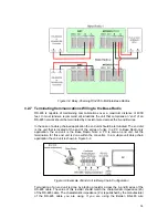
3.2.5.2  Wiring the DB-9 RS-485 Cable to the Base Radio 

Using the converter’s Male DB-9 Connector chart wire up a 

Female 

DB-9 connector such 

that Pins 2 and 9 (Tx+ and Rx+) go to the Base Radio’s WMT terminal A, and Pins 1 and 
3 (Tx- and Rx-) go to the Base Radio’s WMT terminal B. (See Figure 3-5 for details on 
WMT Terminal A and B). 

USB Converter’s Male DB-9 Connector 

PIN # SIGNAL
1 Rx- 
2 Tx+ 
3 Tx- 
4 NC 
5 GND 
6 NC 
7 NC 
8 NC 
9 Rx+ 


3.2.5.3  USB Driver Un-installation 

1. 

Unplug the converter from the PC’s USB Port. 

2. 

Insert the converter’s driver CD used for installation. 

3. 

Run the FTDIUNIN.EXE program. 

4. 

Restart the PC. 

3.2.6  Daisy-Chaining Multiple Base Radios to Single RS-485/Power 

Two or more Base Radios may be placed on a single RS-485 communication line, and a 
single power supply line (provided the power supply and wiring can handle the load). This 
section will provide the information needed to daisy-chain multiple Base Radios. 
However, be sure to complete Section 3.2.8 on correct Base Radio termination if doing 
so. 


12

Содержание ISM BAND XYR 5000 LINE

Страница 1: ...Base Radio User Guide 900 MHz ISM Band FCC XYR 5000 Line 34 XY 25 05 Rev 4 08 06 ...

Страница 2: ...II ...

Страница 3: ...pically Radiated Power is not more than that required for successful communication The installer of this radio equipment must ensure that the antenna is located or pointed such that it does not emit RF field in excess of Health Canada limits for the general population consult Safety Code 6 obtainable from Health Canada s website www hc sc gc ca rpb FCC Certification This product is a frequency hop...

Страница 4: ...ontrol customers Honeywell Organization WWW Address URL e mail Corporate http www honeywell com Industrial Measurement and Control http content honeywell com imc International http www honeywell com Business global asp Field Instruments http www honeywell com imc Technical Assistance Center ACE Honeywell com e mail Telephone Contact us by telephone at the numbers listed below Organization Phone Nu...

Страница 5: ...ng to the Base Radio 14 3 2 8 Grounding the Base Radio 15 3 2 9 High Gain Antenna 15 4 GENERAL CONFIGURATION 16 4 1 BASE RADIO DISPLAYED MESSAGES 16 4 1 1 The Read Only Sequence 16 4 2 OVERALL CONFIGURATION MENU MAP 17 4 3 SETTING THE USER PASSWORD 18 5 CONFIGURING THE RF COMMUNICATIONS 19 5 1 RF CHANNEL SELECTION 19 5 2 RF BAUD RATE SELECTION 20 5 3 HIGH RF ID SETTING 21 6 CONFIGURING THE MODBUS ...

Страница 6: ...nsmitter Registers 30 6 5 TRANSMITTER HOLDING REGISTERS 31 6 5 1 Device ID Mapping Mode 31 6 5 2 Register Mapping Mode 31 6 5 3 Transmitter Device Type Holding Registers 32 6 5 4 Transmitter Device Status Registers 33 6 6 SQUARE ROOT FUNCTION 33 7 TECHNICAL SPECIFICATIONS 34 APPENDIX A NAVIGATING THE MENUS 36 APPENDIX B BASE RADIO MENU MAP 37 APPENDIX C MODBUS REGISTER DEFINITIONS 38 VI ...

Страница 7: ...ios 14 Figure 3 9 Example of End Unit in Daisy Chain Configuration 14 Figure 3 10 Example of Correct Termination Resistor Setup 15 Figure 4 1 Base Radio Power Up and Operations LCD Sequences 16 Figure 4 2 The Read Only Sequence 17 Figure 4 3 Overall Configuration Menu Map 17 Figure 5 1 Menu Map to RF Channel Setting 19 Figure 5 2 Menu Map to RF Baud Rate Setting 20 Figure 6 1 Menu Map to Modbus Ba...

Страница 8: ...placed in service 6 Configuring the MODBUS Communications This section covers the various Base Radio settings that must be configured for Modbus communication such as baud rate parity device ID s and register mapping modes Also covered in this section is a brief discussion of the Modbus communications protocol and Modbus commands that are used with this device Modbus register locations are also di...

Страница 9: ...ts are assembled with accessories when shipped Inspect the shipment carefully if you think that something is missing This is rare as we take considerable care to pack units for shipment but it does sometimes happen Please give us a call and we may be able to resolve this matter quickly over the phone Please note that the carrier will not honor any claims for damage unless all shipping materials ar...

Страница 10: ...verall Wiring Schematic 1 Wire 24VDC power to the Base Radio using the power terminals on either the WMT or the Modbus connection Do not apply power to both sets of terminals 2 Wire WMT RS 485 communications to the left terminal of the Base Radio 3 Wire Modbus RS 485 communications to the right terminal of the Base Radio 4 Place the terminating resistor between terminals A and B if the Base Radio ...

Страница 11: ...e on the Base Radio check the following Is the Base Radio set to the above listed configurations Are all the Transmitters on Are the Transmitters set to the matching RF configurations see Section 5 of Transmitter and Base Radio User Manuals Are the Base Radio and Transmitters unable to communicate due to obstructions or distance see Transmitter Manual Transmitter Placement section Warning If the T...

Страница 12: ...ceable location Most often these problems can be avoided with some thought at the time of installation The practices noted below are generally recommended but they can only act as guidelines and cannot cover all possible variations The final installation must be made at the discretion and approval of the user You must be the judge of the actual installation Warning During installation do not apply...

Страница 13: ...uctions Only place the Base Radio in ambient operating temperatures of 40 F to 185 F 40 C to 85 C Make sure you have power and communication to the Base Radio available see 3 2 Electrical Installation Because there are so many setup possibilities we cannot cover them all A correct setup would make sure that the above warnings are heeded and that the Transmitter and Base Radio are capable of commun...

Страница 14: ... Wiring to the Base Radio 3 2 8 Grounding the Base Radio 3 2 9 High Gain Antenna Warning Remember to turn off all power BEFORE attaching the Base Radio wires 3 2 1 Electrical Specifications 24VDC Power Supply with 0 5 Amp minimum output Recommend 22AWG Power Supply wire 2 Wire RS 485 Serial Communications Cable Recommend Belden 3105A shielded and protected 22AWG or equivalent 120 Ohm 5 W resistor ...

Страница 15: ...ions are on To begin the electrical installation first remove the explosion proof housing cover from the Base Radio if you have not already done so Point the Base Radio antenna away from you and look at the green PC Board found directly underneath the NEXT and ENTER buttons You should see two terminal blocks and some labels as shown in Figure 3 3 Figure 3 3 Terminal Block Labels 8 ...

Страница 16: ...dio The Honeywell Base Radio is designed to use a 24 VDC power supply at a minimum of 0 5 Amps Honeywell offers a DIN rail mountable 100 240VAC 50 60Hz to 24VDC transformer for this purpose AIC For more information contact your Honeywell Representative The Common or Negative wire should be placed in the left most slot labeled GND on the PC Board of the terminal block in Figure 3 4 The Positive wir...

Страница 17: ...e daisy chained See Section 3 2 6 Note that Base Radios daisy chained must be set to different RF Channels to communicate properly on the same wire 3 2 4 Wiring the RS 485 232 Converter to the Base Radio Honeywell offers an optically isolated surge protected DIN Rail mountable RS 485 232 converter AIC Because there are many RS 485 232 Converters available please see your converter s instruction ma...

Страница 18: ...ng the RS 485 USB Converter to the Base Radio Note The RS 485 cable should NOT be connected to the RS 485 USB converter before the converter drivers have been installed Honeywell also offers a non optically isolated RS 485 to USB converter The USB Converter provides easy connectivity between the PC and standard communication ports not requiring PC reconfiguration assignment of IRQs or jumper setti...

Страница 19: ...be displayed Select OK 3 2 5 2 Wiring the DB 9 RS 485 Cable to the Base Radio Using the converter s Male DB 9 Connector chart wire up a Female DB 9 connector such that Pins 2 and 9 Tx and Rx go to the Base Radio s WMT terminal A and Pins 1 and 3 Tx and Rx go to the Base Radio s WMT terminal B See Figure 3 5 for details on WMT Terminal A and B USB Converter s Male DB 9 Connector PIN SIGNAL 1 Rx 2 T...

Страница 20: ...er each Base Radio should be wired in parallel to the next while making sure power is not supplied from two separate supplies to any single Base Radio A typical wiring setup is shown in Figure 3 7 below GND 24V B A GND 24V B A Power Supply Base Radio 1 GND 24V B A GND 24V B A Base Radio 2 Figure 3 7 Daisy Chaining Power to Multiple Base Radios 3 2 6 2 Daisy Chaining RS 485 to Multiple Base Radios ...

Страница 21: ... at the end of the series of units In a PC to Base Radio only application the end unit is the Base Radio Note a PC is also an end unit but the termination for this end unit is done within the converter In a multiple unit daisy chain application the end unit is shown in Figure 3 9 Figure 3 9 Example of End Unit in Daisy Chain Configuration Termination of an end unit is done by placing a resistor ac...

Страница 22: ... 8 Grounding the Base Radio ts on your Base Radio the Base Radio housing must Possible grounded objects include The building s metal frame work Any electrical conduit A suitable grounding or lightning rod 3 2 9 High Gain Antenna ilable for the Base Radio This antenna generally doubles the In order to assure safety requiremen be grounded We have provided a grounding screw located on the left side o...

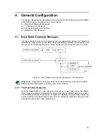
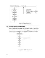
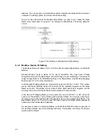
Страница 23: ...n go into an Operations Sequence These Sequences are shown in Figure 4 1 below Figure 4 1 Base Radio Power Up and Operations LCD Sequences Note During configuration and testing keep Transmitters at least six feet from the Base Radio and other Transmitters to ensure good communications 4 1 1 The Read Only Sequence Once the Base Radio is in the Operations Sequence a user may access the READ ONLY Seq...

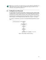
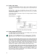
Страница 24: ...rall Configuration Menu Map A complete Base Radio Menu Map is shown in Appendix B Below is an overall view of the configuration menu to aid the user in setting up the Base Radio for proper operation Figure 4 3 Overall Configuration Menu Map 17 ...

Страница 25: ...ers from making changes to the Base Radio Any user may still view some of the Base Radio settings by pressing the ENTER key during the Operations Sequence and viewing the Read Only Sequence The password is a four digit password The factory default is 0000 If you wish to select a different password follow the Base Radio Menu Map shown in Figure 4 5 to change it If you forget your password you must ...

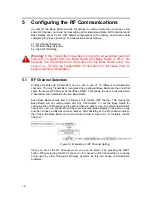
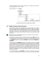
Страница 26: ...t communication channels The only Transmitters recognized by a particular Base Radio are the units that share the same RF Channel as that Base Radio This allows the user to decide which Transmitters communicate with each Base Radio Each Base Radio comes from the factory set to the RF OFF channel This means the Base Radio will not communicate with any Transmitters To set the Base Radio for communic...

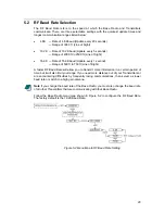
Страница 27: ...to 750 ft Line of Sight A faster RF Baud Rate will allow you to transmit more information in a certain period of time but it will also limit your range If you need more distance out of your Transmitters or are encountering difficulties by frequently losing communications then select a slower baud rate or switch to a high gain antenna Note If you change the baud rate of the Base Radio you must also...

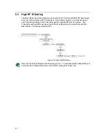
Страница 28: ...nd 100 corresponding to the Transmitter with the highest RFID on the system Any Transmitter with an RFID set above the HI RFID setting will not communicate with the Base Radio The factory default is 001 Figure 5 3 High RFID Setting Note that the Output Modules with firmware prior to 1 7 purchased before May 2006 will not work with the Base Radio when the HI RFID setting is set above 50 21 ...

Страница 29: ...4 1 Base Radio Device Type Registers 6 4 2 Base Radio Device Status Registers 6 4 3 Base Radio On Offline Transmitter Registers 6 5 Transmitter Holding Registers 6 5 1 Device ID Mapping Mode 6 5 2 Register Mapping Mode 6 5 3 Transmitter Device Type Holding Registers 6 5 4 Transmitter Device Status Registers Note This device supports Modbus RTU Binary communications Note that the ASC II transmissio...

Страница 30: ...e section 6 1 4 for more information In the Register Mapping Mode you may select any device ID from 1 to 247 This number will be the device Modbus device ID at which all the readable registers for the Base Radio and every Transmitter will be located More detail about each register and its meaning can be found in the Modbus Communications Protocol section In the Device ID Mapping Mode you may selec...

Страница 31: ...p shown in Figure 6 2 to configure the device ID The factory default is 001 Figure 6 2 Menu Map to Modbus Device ID Setting Note The Base Radio provides different Device ID modes in order to support a wide range of Modbus equipment In the Register Mapping Mode the data for the Base Radio and all Transmitters are located under a single device ID This ID may be any allowable Modbus address between 1...

Страница 32: ...ID setting see Section 4 2 There are two possible mapping modes that can be used The first is the Device ID mapping mode Using this mode gives the Base Radio a device ID equal to its device ID setting There are then 10 Modbus registers located at this device ID for this Base Radio Each Transmitter communicating with this Base Radio is then located at device ID X where X is the RF ID of the Transmi...

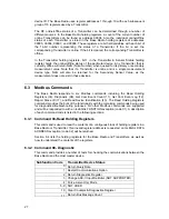
Страница 33: ...he DEV ID menu item Transmitters can be configured either to be assigned to an individual Modbus device ID or to holding registers within the Base Radio device ID through the appropriate selection in the MODMAP menu item There are two MODMAP modes available DEVMODE and REGMODE If the device ID mode DEVMODE is selected a Transmitter s data may be accessed with the Modbus Read Holding Register Comma...

Страница 34: ... these devices 6 3 Modbus Commands The Base Radio responds to six Modbus commands including the Read Holding Registers 03 Diagnostic 08 Get Com Event Count 11 Get Com Event Log 12 Report Slave ID 17 and Read Device Identification 43 The Read Holding Registers command provides the bulk of the functionality with the remaining commands being used for diagnostics troubleshooting purposes No other Modb...

Страница 35: ...ent Log This command returns a status word communications event counter message count and a field of bytes from the communications event log The status word and communications event counter are identical to those returned by Command 11 Get Com Event Counter above The message count is a count of the total number of messages received by this device including messages intended specifically for this d...

Страница 36: ...ed Int 00003 Number of Transmitters Expected 16 Bit Unsigned Int 00004 Number of Transmitters Communicating 16 Bit Unsigned Int 00005 Online Offline Status Of Transmitters 1 16 16 Bit Unsigned Int 00006 Online Offline Status Of Transmitters 17 32 16 Bit Unsigned Int 00007 Online Offline Status Of Transmitters 33 48 16 Bit Unsigned Int 00008 Online Offline Status Of Transmitters 49 50 16 Bit Unsign...

Страница 37: ...dio Device Status 1 Base Radio Online 2 Reserved For Future Use 6 4 3 Base Radio On Offline Transmitter Registers Below are the values for the Online Offline Status of Transmitters 1 16 holding register in the Base Radio The other online offline status holding registers hold the status of the remaining Transmitters with RF IDs 17 through 50 Value Transmitter Device 1 Transmitter 1 Online Status 2 ...

Страница 38: ...egister contains the value 6 We can subtract 4 to get 2 Then we can subtract 2 to get 0 Thus Transmitter 2 and 3 are online but Transmitters 1 and 4 are offline 6 5 Transmitter Holding Registers The following are the Transmitter holding registers when used in the Device ID Mapping Mode First Table and the Register Mapping Mode Second Table 6 5 1 Device ID Mapping Mode Transmitter Holding Registers...

Страница 39: ...2 Pressure Transmitter 3 Dual 0 10V Input Transmitter 4 Dual 4 20mA Input Transmitter 5 Thermocouple Transmitter 6 Reserved 7 Level Sensor Transmitter 8 Split RTD Transmitter 9 Split Pressure Transmitter 10 Split Dual Thermocouple Transmitter 11 Differential Pressure Transmitter 100 IN H20 12 Split Differential Pressure Transmitter 100 IN H20 13 Differential Pressure Transmitter 300 IN H20 14 Spli...

Страница 40: ...e the holding register reads 9 then subtract 8 and get 1 Then subtract 1 from 1 and get 0 Thus from the list above we have a Sensor Error Condition and the Transmitter is online 6 6 Square Root Function The Square Root Function only works with the Differential Pressure Transmitter When the DP Transmitter is in Orifice mode a Square Root calculation is performed You have the option to display the S...

Страница 41: ...ristic Baked enamel explosion proof weather proof and corrosion proof housing Electromagnetic Compatibility CE Compliance Operates within specification in fields from 80 to 1 000 MHz with field strengths to 10 V m Meets EN 50082 1 general immunity standard and EN 55011 compatibility emissions standard Industrial Certification Rated for industrial use FM rated 40 F to 185 F 40 C to 85 C CSA Rated 4...

Страница 42: ...Figure 7 1 Overall Base Radio Dimensions 35 ...

Страница 43: ...e NEXT button is then used to step through menu options and the ENTER button is used to enter a submenu of what is displayed on the LCD at that time If no button is pressed within a 30 second period the unit goes back to the normal display mode If you enter a submenu that requires a numerical input such as 001 the leftmost 0 will be blinking This indicates that pressing the NEXT button will increm...

Страница 44: ...Appendix B Base Radio Menu Map Figure A 1 Base Radio Menu Map 37 ...

Страница 45: ...ry at 0 degC MegaPascals 237 megapascals InH2OAt4C 238 inches of water at 4 degC MMH2OAt4C 239 millimeters of water at 4 degC Volumetric Flow Units CuFtPerMin 15 cubic feet per minute GalPerMin 16 gallons per minute LiterPerMin 17 liters per minute ImpGalPerMin 18 imperial gallons per minute CuMeterPerHr 19 cubic meter per hour GalPerSec 22 gallons per second MillionGalPerDay 23 million gallons pe...

Страница 46: ... document HCF_SPEC 183 Time Units Min 50 minutes Sec 51 seconds Hr 52 hours Day 53 days Mass Units Gram 60 grams KG 61 kilograms MetricTon 62 metric tons Pound 63 pounds ShortTon 64 short tons LongTon 65 long tons Ounce 125 ounce Mass Flow Units GramPerSec 70 grams per second GramPerMin 71 grams per minute GramPerHr 72 grams per hour KGPerSec 73 kilograms per second KGPerMin 74 kilograms per minut...

Страница 47: ...y Units DegPerSec 117 degrees per second RPS 118 revolutions per second RPM 119 revolutions per minute Energy Work Units NM 69 newton meter DekaTherm 89 deka therm FtLbForce 126 foot pound force KWHr 128 kilo watt hour MCal 162 mega calorie MJ 164 mega joule BTU 165 british thermal unit Force Units Newton 68 newton Power Units KW 127 kilo watt HP 129 horsepower MCalPerHr 140 mega calorie per hour ...

Страница 48: ...LitersPerLiter 154 milli liters per liter MicroLitersPerLiter 155 micro liters per liter Volume per Mass Units DegBalling 107 degrees balling CuFtPerLb 152 cubic feet per pound Concentration Units DegBrix 101 degrees brix PerSolidsPerWt 105 percent solids per weight PerSolidsPerVol 106 percent solids per volume PfPerVol 108 proof per volume PfPerMass 109 proof per mass PPM 139 parts per million PP...

Страница 49: ... 16986 Honeywell Industrial Measurement and Control 2500 W Union Hills Drive Phoenix AZ 85027 ...

Отзывы: