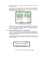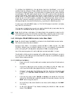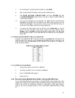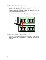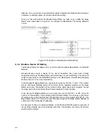
To configure the 485LDRC9 to the appropriate baud rate (38.4Kbaud), a set of dip
switches must be configured. These switches can be found on the side of the converter.
The first four switches should be in the ON position to indicate that the communications
are half-duplex. The fifth switch should also be in the OFF position as this activates the
120 Ohm termination resistor within the converter. This terminator is only useful for long
RS-485 buses, or other calculated circumstances. Finally, switches six, seven, and eight
should be set to the OFF position to indicate the correct baud rate. (Note: An 8.2 K
resistor (R11) has been installed at the factory to achieve these higher baud rates. If you
did not purchase the converter from the factory, you will need to install the resistor.)
To wire power to the 485LDRC9, place a +10 to 30 VDC supply to terminal F, and place
the ground (V-) to terminal C.
The final step in installing the converter is to attach a DB-9 RS-232 (serial) cable from the
converter to an available serial port on your computer.
Note
The RS-485 bus is half-duplex. If the Base Radio in the application is wired to a RS-
485 to RS-232 converter, the A (Tx+/Rx+) and B (Tx-/Rx-) wires may need to be crossed
for correct operation. Please see the converter’s manual for further instructions.
3.2.5 Wiring the RS-485/USB Converter to the Base Radio
Note
The RS-485 cable should
NOT
be connected to the RS-485/USB converter before
the converter drivers have been installed.
Honeywell also offers a non-optically isolated RS-485 to USB converter. The USB
Converter provides easy connectivity between the PC and standard communication
ports, not requiring PC reconfiguration, assignment of IRQs, or jumper settings.
Use of this device requires a PC with a USB port compliant with USB 1.1 or later.
The RS-485 to USB converter is equipped with a USB cable and a USB type A connector
for connection to a PC USB port and a male DB-9 for connection to an RS-485 equipped
data or communication terminal.
3.2.5.1 USB Driver Installation
1.
Power on the PC. Verify the USB port is enabled and insert the CD that has been
provided.
2.
Connect the USB cable of the converter to the USB port of the PC. Make sure
not to have the RS-485 cable plugged into the converter at this time.
3.
Windows™ should detect the USB device, and if the driver does not already exist
on the PC the “
Add New Hardware Wizard
” will be displayed. Click the
NEXT
button.
4.
From this new screen select “
Specify a Location
” and specify the PC’s drive
letter for the CD-ROM drive where the provided CD has been inserted. Click the
NEXT
button to begin the search.
5.
Once the drivers have been located a new screen will be displayed. Click
NEXT
to continue.
6.
At this point Windows™ has finished installing the RS-485 to USB converter
drivers. Click
FINISH
.
11
Содержание ISM BAND XYR 5000 LINE
Страница 1: ...Base Radio User Guide 900 MHz ISM Band FCC XYR 5000 Line 34 XY 25 05 Rev 4 08 06 ...
Страница 2: ...II ...
Страница 42: ...Figure 7 1 Overall Base Radio Dimensions 35 ...
Страница 44: ...Appendix B Base Radio Menu Map Figure A 1 Base Radio Menu Map 37 ...
Страница 49: ... 16986 Honeywell Industrial Measurement and Control 2500 W Union Hills Drive Phoenix AZ 85027 ...


