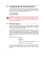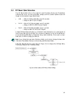
3 Installation
This section discusses both the mechanical and electrical aspects of installation. It is
divided into the following sections:
3.1: Mechanical Installation
3.2: Electrical Installation
3.1 Mechanical
Installation
In this section, the mechanical installation instructions are discussed for the various setup
capabilities of the Base Radio. The subsections are as follows:
3.1.1 Base Radio Positioning
The Honeywell Base Radio is a rugged device, which provides optimal performance
when installed with careful consideration. Installation practices greatly affect the life that
you can expect from your Honeywell Base Radio. The main considerations for installation
are covered below.
Give careful consideration to the environment where you will be installing the devices.
Avoid installations that expose the device to excess temperature, high vibration,
considerable shock, or exposure to dripping condensate or corrosive materials. Also
avoid installing the device in an unserviceable location.
Most often these problems can be avoided with some thought at the time of installation.
The practices noted below are generally recommended, but they can only act as
guidelines and cannot cover all possible variations.
The final installation must be made at the discretion and approval of the user. You must
be the judge of the actual installation.
Warning!
During installation do not apply force to the instrument housing
or antenna. Use a proper wrench for all installations. Failure to use correct
installation procedures can cause damage to the Base Radio.
3.1.1 Base Radio Positioning
Correct positioning of the Base Radio will ensure the best performance of the device.
Because the Base Radio is the central communication device of all Transmitters that are
assigned to it, the Base Radio should be located in an area that is somewhat central to all
of the Transmitters.
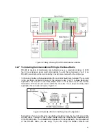
Figure 3-1 is a picture of a general Base Radio layout. The maximum distance is
determined by a number of factors, including the Baud Rate Setting. When planning the
positioning of the Base Radio, try to place the Base Radio in a location with an
unobstructed view to the most Transmitters possible.
5
Содержание ISM BAND XYR 5000 LINE
Страница 1: ...Base Radio User Guide 900 MHz ISM Band FCC XYR 5000 Line 34 XY 25 05 Rev 4 08 06 ...
Страница 2: ...II ...
Страница 42: ...Figure 7 1 Overall Base Radio Dimensions 35 ...
Страница 44: ...Appendix B Base Radio Menu Map Figure A 1 Base Radio Menu Map 37 ...
Страница 49: ... 16986 Honeywell Industrial Measurement and Control 2500 W Union Hills Drive Phoenix AZ 85027 ...


