11
ENGLISH
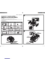
Installing the rear panel
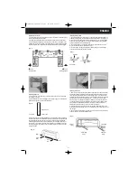
1. Choose the location of the rear panel according to the indoor unit location, piping
direction and drainage hose direction.
2. Holding the panel against the wall horizontally, mark the mount hole positions.
3. After drilling and plugging the mounting holes, screw the mounting plate to the
wall. Make sure it is securely fixed to the wall. Be aware of the weight that this plate
is intended to take. Have a look at the technical specifications for product weights.
Installing drainage hose
1. The drainage hose exists at the indoor unit and must be installed downwards. To
extend the drainage hose, use the additional white drainage hose with a length of 4
m and put it on the end bit of the short grey drainage hose (1 m). To avoid leakage,
use a hose clamp with a diameter of 19 mm for connecting the existing drainage
hose with the additional white drainage hose.
2. The drainage hose must not be bent, wrenched or risen. Furthermore its end
must not be flooded by water (as shown in Fig. 3).
3. To avoid noise of the longer drainage hose passing indoor unit, this drainage
hose should be encased by insulation material.
Installing indoor unit
1. Refer to Fig. A for routing the pipes (liquid and gas pipe). To avoid obstruction or
damage bend them gently. During routing the pipes (liquid and gas pipe) from the
left or right side of the indoor unit, cut out the tailing of pipe on the left side of the
chassis of the main unit as shown in fig. 4c. Cut out tailing 1 and 2 when connection
pipe and power cord are routed both. Methods 1, 2, 3 and 4 are recommended.
NOTE: In order not to damage the piping, we recommend to only bend them once
very gently. Furthermore it is essential when you extend the pipes (liquid and gas
pipe), that you fill in additional coolant into the system, in order to achieve an
effective and correct functioning of the air conditioner (150g/2m).
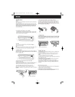
2. Hang the suspension slot, positioned on the rear side of the indoor unit, on the
hooks of the rear panel (shown in fig. 6). It is necessary to check if the indoor unit is
firm enough.
3. Ensure that the install height of the indoor unit is 2 m or more above the floor as
shown in the figure “Select the installing place”.
80 mm
Left piping hole
80 mm
Right piping hole
(Fig. 1)
Wrenched
Bent
Don’t flood it.
(Fig. 3)
X
X
1 Left Piping
2 Rear Left
Piping
3 Right
Piping
4 Rear Right
Piping
(Fig. A)
(Fig. 2)
Left
Right
Right
Rear
Lower
Left
Open the piping hole
1. As shown in fig. 2, the pipe can go out at 4 directions, choose one among them
according to your need.
2. After confirmed the location of piping hole according to fig.1, drill a hole (80 mm
diameter) through the wall with a slant downward.
3. Before you will pass the connection piping, wiring and quick connector through
the hole, wrap them with the delivered wrap tape in order to avoid these parts being
damaged when passing through the hole. The part of the connection piping and
wiring staying within the hole, should be wrapped by the wrap tape all the time of
use in order to avoid them to accrue with the insulation. The remaining part of the
connection piping, wiring and the quick connector outside of the hole must be free
of that wrap tape.
Indoor Unit
Outdoor Unit
Downward Tilt
(Fig. 1a)
HW-QUICK12E_GB_OM.qxd 4/2/07 12:04 PM Page 11


