background image

User Manual of Explosion-Proof Bullet Camera 


79


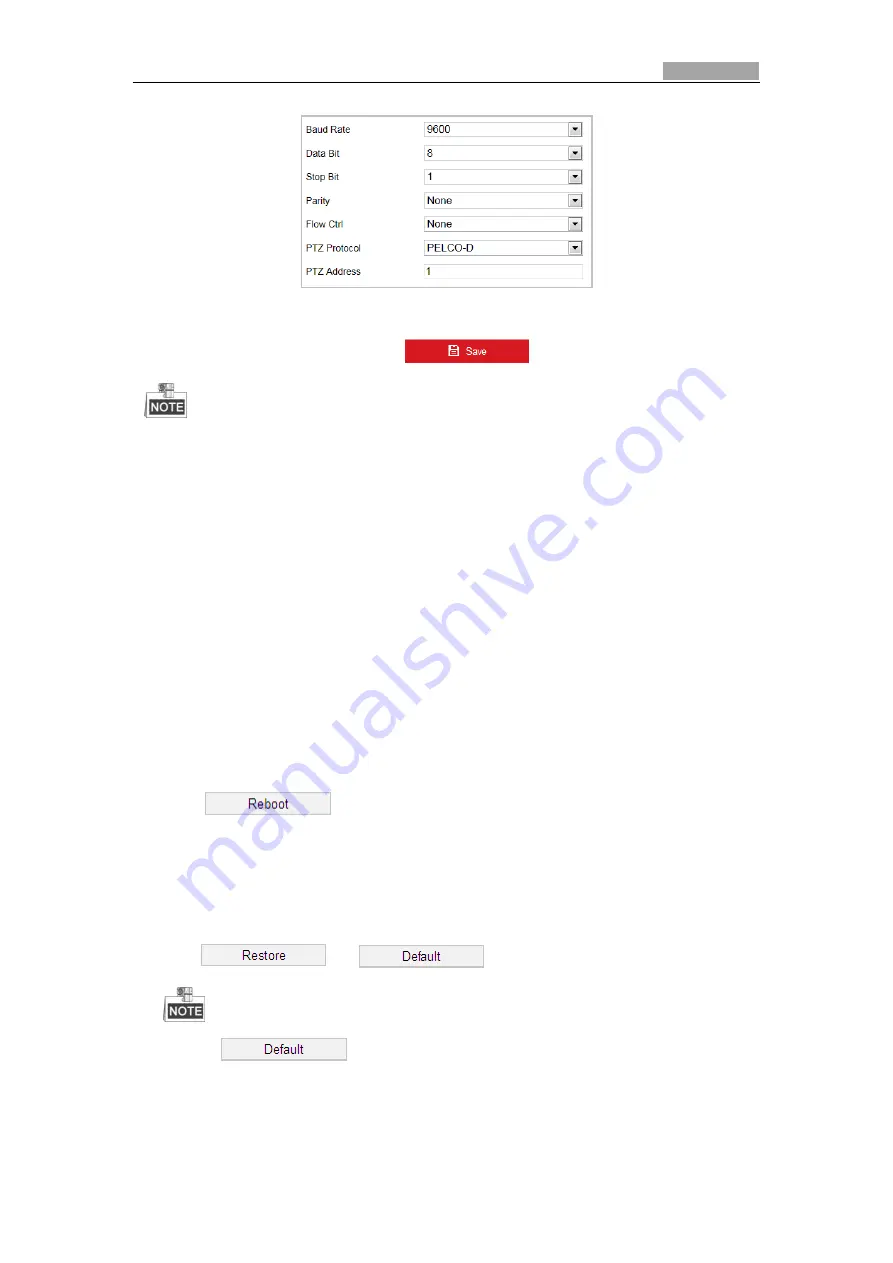
Figure 6-45


RS-485 Settings 

2.


Set the RS-485 parameters and click 

  to save the settings. 


The Baud rate, PTZ Protocol and PTZ Address parameters of the camera should be exactly the 
same as those of the control device. 

About 

Click 

View License

, you can check Open Source Software Licenses. 

6.4.2


Maintenance 

Upgrade & Maintenance 


Rebooting the Camera 

Steps: 

1.


Enter the Maintenance interface: 

2.


Configuration 

System

 >

 Maintenance > Upgrade & Maintenance:


3.


Click 


to reboot the network camera. 


Restoring Default Settings 

Steps: 

1.


Enter the Maintenance interface:


Configuration 

System

 >

 Maintenance > Upgrade & Maintenance: 

2.


Click 

  or 

  to restore the default settings. 


Clicking 

  restores all the parameters to default settings including the IP 

address and user information. Use this button with caution. 

Содержание HEICC-2736-WI

Страница 1: ...HEICC 2736 WI Explosion Proof Bullet Camera User manual ...

Страница 2: ...likely to cause harmful interference in which case the user will be required to correct the interference at his own expense FCC Conditions This device complies with part 15 of the FCC Rules Operation is subject to the following two conditions 1 This device may not cause harmful interference 2 This device must accept any interference received including interference that may cause undesired operatio...

Страница 3: ...ll be connected reliably Ground wire cross sectional area of not less than the phase connector cross sectional area level at least 4 mm2 All the electrical operation should be strictly compliance with the electrical safety regulations fire prevention regulations and other related regulations of the nation and region Make sure that the power has been disconnected before you wire install or disassem...

Страница 4: ...ic radiation To avoid heat accumulation good ventilation is required for operating environment Keep the camera away from liquid while in use While in delivery the camera shall be packed in its original packing or packing of the same texture Regular part replacement a few parts e g electrolytic capacitor of the equipment shall be replaced regularly according to their average enduring time The avera...

Страница 5: ...RAMETERS 10 4 2 LIVE VIEW PAGE 11 4 3 STARTING LIVE VIEW 12 4 4 OPERATING PTZ CONTROL 14 4 4 1 PTZ Control Panel 15 4 4 2 Auxiliary Functions 16 4 4 3 Setting Calling a Preset 18 4 4 4 Setting Calling a Patrol 20 4 4 5 One touch Patrol 21 4 4 6 Setting Calling a Pattern 22 4 5 PLAYBACK 23 4 5 1 Play Back Video Files 23 4 5 2 Downloading Video Files 25 4 6 PICTURES 25 CHAPTER 5 SYSTEM CONFIGURATION...

Страница 6: ... CONFIGURING NETWORK SETTINGS 49 6 1 1 Basic Settings 49 6 1 2 Advanced Settings 54 6 2 CONFIGURING VIDEO AND AUDIO SETTINGS 63 6 2 1 Configuring Video Settings 63 6 2 2 Configuring Audio Settings 65 6 2 3 Configuring ROI Settings 65 6 3 CONFIGURING IMAGE SETTINGS 67 6 3 1 Configuring Display Settings 67 6 3 2 Configuring OSD Settings 72 6 3 3 Configuring Text Overlay Settings 74 6 3 4 Configuring...

Страница 7: ...es during the day And as light diminishes at night the cameras switch to night mode and deliver black and white images with high quality Slow Shutter In slow shutter mode the shutter speed will automatically slow down in low illumination conditions to maintain clear video images by extending the exposure time The feature can be enabled or disabled Backlight Compensation BLC If you focus on an obje...

Страница 8: ...fferent levels of permission in the admin login status Multiple users are allowed to access and control the same camera via network simultaneously 3D Digital Noise Reduction Comparing with the general 2D digital noise reduction the 3D digital noise reduction function processes the noise between two frames besides processing the noise in one frame The noise will be much less and the video will be c...

Страница 9: ...mera over the LAN If you want to set the network camera via a WAN Wide Area Network refer to Section 2 2 Setting the Network Camera over the WAN 2 1 Setting the Network Camera over the LAN Purpose To view and configure the camera via a LAN you need to connect the camera in the same subnet with your computer and install the SADP or client software to search and change the IP of the network camera F...

Страница 10: ...amera Activation via web browser activation via SADP and activation via client software are supported Activation via Web Browser Steps 1 Power on the camera and connect the camera to the network 2 Input the IP address into the address bar of the web browser and click Enter to enter the activation interface The default IP address of the camera is 192 168 1 64 Figure 2 3 Activation Interface Web 3 C...

Страница 11: ...omplete security question settings during camera activation Or admin user can go to User Management interface to set up the function 2 2 Setting the Network Camera over the WAN Purpose This section explains how to connect the network camera to the WAN with a static IP or a dynamic IP 2 2 1 Static IP Connection Before you start Apply a static IP from an ISP Internet Service Provider With the static...

Страница 12: ...ess you can connect the network camera to a modem or a router Connecting the network camera via a router Steps 1 Connect the network camera to the router 2 In the camera assign a LAN IP address the subnet mask and the gateway Refer to Section 2 1 2 for detailed LAN configuration 3 In the router set the PPPoE user name password and confirm the password For your privacy and to better protect your sy...

Страница 13: ...m You need to configure the PPPoE parameters of the network camera Refer to Section 6 1 1 Configuring PPPoE Settings for detailed configuration The obtained IP address is dynamically assigned via PPPoE so the IP address always changes after rebooting the camera To solve the inconvenience of the dynamic IP you need to get a domain name from the DDNS provider E g DynDns com Follow the steps below fo...

Страница 14: ...p right of login interface 5 Input the user name and password and click The admin user should configure the device accounts and user operator permissions properly Delete the unnecessary accounts and user operator permissions The device IP address gets locked if the admin user performs 7 failed password attempts 5 attempts for the user operator Figure 3 1 Login Interface 6 Install the plug in befor...

Страница 15: ...User Manual of Explosion Proof Bullet Camera 9 Figure 3 2 Download and Install Plug in ...

Страница 16: ...iew Parameters Set the protocol type play performance rules and image format Protocol Type TCP UDP MULTICAST and HTTP are selectable TCP Ensures complete delivery of streaming data and better video quality yet the real time transmission will be affected UDP Provides real time audio and video streams MULTICAST It s recommended to select the protocol type to MULTICAST when using the Multicast functi...

Страница 17: ...e view to Set the saving path of the manually captured pictures in interface Save snapshots when playback to Set the saving path of the captured pictures in interface Save clips to Set the saving path of the clipped video files in interface You can click Browse to change the directory for saving video files clips and pictures You can click Open to directly open the video files clips and pictures 3...

Страница 18: ...e View Window Display the live video Toolbar Operations on the live view page e g live view capture record audio on off regional exposure regional focus etc PTZ Control Panning tilting focusing and zooming actions of the network The lighter wiper one touch focus and lens initialization control Preset patrol pattern Set and call the preset patrol pattern for the camera Live View Parameters Configur...

Страница 19: ...Manual start stop recording Mute audio on and adjust volume Start stop digital zoom Enable disable regional exposure Enable disable regional focus Double click on the live video to switch the current live view into full screen or return to normal mode from the full screen Click to select from and display live video in 4 3 16 9 original self adaptive window size Click to select from and display liv...

Страница 20: ...mal picture Click the on the toolbar to enter the regional exposure operation mode and the icon turns into Then drag the mouse to draw a rectangle on the image as the desired exposure region Click the on the toolbar to enter the regional focus operation mode and the icon turns into Then drag the mouse to draw a rectangle on the image as the desired focus region Click to display the Drag the slider...

Страница 21: ... movements Click the zoom iris focus buttons to realize lens control Figure 4 4 PTZ Control Panel Table 4 2 Descriptions of PTZ Control Panel Button Name Description PTZ Control Panel Hold and press the direction button to pan tilt the camera Click and the camera keeps panning the icon turns into Click the icon again to stop the camera Zoom out in Click the lens zooms in click and the lens zooms o...

Страница 22: ...ne touch patrol and one touch park Speed Adjustment Adjust speed of pan tilt movements Preset Refer to 4 4 3 for detailed information of setting preset Patrol Refer to 4 4 4 for detailed information of setting patrol Pattern Refer to4 4 6 for detailed information of setting pattern Buttons on the Preset Patrol Patterns interface Table 4 3 Descriptions of Buttons Buttons Description Start the selec...

Страница 23: ...on the toolbar of live view interface 2 Operate the 3D positioning function Click a position of the live video The corresponding position will be moved to the center of the live video Hold down the left mouse button and drag the mouse to the lower right on the live video The corresponding position will be moved to the center of the live video and zoomed in Hold down the left mouse button and drag ...

Страница 24: ...to the right or left Tilt the camera up or down Zoom in or out Refocus the lens 3 Click to finish the setting of the current preset 4 Edit a preset name by double clicking on the default name such as preset 1 The pre defined presets are named already and not configurable Refer to the user manual for detailed function description 5 You can click to delete the preset You can configure up to 256 pres...

Страница 25: ...ops 34 Back to initial position 93 Set limit stops manually 35 Call patrol 1 94 Remote reboot 36 Call patrol 2 95 Call OSD menu 37 Call patrol 3 96 Stop a scan 38 Call patrol 4 97 Start random scan 39 Day mode IR cut filter in 98 Start frame scan 40 Night mode IR cut filter out 99 Start auto scan 41 Call pattern 1 100 Start tilt scan 42 Call pattern 2 101 Start panorama scan 43 Call pattern 3 102 ...

Страница 26: ...Select a patrol number from the list and click 3 Click to enter the adding interface of preset as shown in Figure 4 9 Figure 4 9 Adding Presets 4 Configure the preset number patrol time and patrol speed Name Description Patrol Time It is the duration staying on one patrol point The camera moves to another patrol point after the patrol time Patrol Speed It is the speed of moving from one preset to ...

Страница 27: ...e touch patrol and the camera moves as the patrol path 8 automatically Steps 1 Set preset No 1 to No 32 Refer to 4 4 3 Setting Calling a Preset for detailed information of setting preset 2 Call preset No 45 and the camera moves as patrol path 8 3 Click to enter the patrol settings interface and start stop one touch patrol edit the patrol time and the speed 4 You can click of the PTZ control panel ...

Страница 28: ...n in Figure 4 12 Figure 4 12 Patterns Settings Interface 3 Click to enable recording the panning tilting and zooming actions 4 Use the PTZ control buttons to move the lens to the desired position after the information of PROGRAM PATTERN REMAINNING MEMORY is displayed on the screen Pan the camera to the right or left Tilt the camera up or down Zoom in or out Refocus the lens 5 Click to save all the...

Страница 29: ...al pan is valid the limit stops and auto flip will be invalid and the 3D positioning operation is not supported 4 5 Playback Purpose This section explains how to view the video files stored in the network disks or memory cards 4 5 1 Play Back Video Files Steps 1 Click on the menu bar to enter playback interface Figure 4 13 Playback Interface 2 Select the date and click ...

Страница 30: ...ng video files Stop Audio on and adjust volume Mute Speed down Download Speed up Playback by frame Enable Disable digital zoom You can choose the file paths locally for downloaded playback video files and pictures in Local Configuration interface Refer to Section 4 1 Configuring Local Parameters for details Drag the progress bar with the mouse to locate the exact playback point You can also input ...

Страница 31: ...ack interface The pop up menu is shown in Figure 4 19 2 Set the start time and end time Click Search The corresponding video files are listed on the left Figure 4 19 Video Downloading interface 3 Check the checkbox in front of the video files that you need to download 4 Click to download the video files 4 6 Pictures Purpose This section explains how to view the captured picture files stored in the...

Страница 32: ...ure 4 20 Picture Interface 2 Select the file type of capturing the pictures from the list as timing alarm motion etc 3 Set the start time and end time Click Search The corresponding picture files will be listed 4 Check the checkbox in front of the files that you need to download 5 Click to download the files ...

Страница 33: ...d scheduled recording In this section you can follow the instructions to configure the scheduled recording By default the record files of scheduled recording are stored in the memory card if supported or in the network disk Steps 1 Enter the Record Schedule settings interface Configuration Storage Schedule Settings Record Schedule Figure 5 1 Recording Schedule Interface 2 Check the checkbox of Ena...

Страница 34: ...record parameters vary depending on different camera models 4 Click OK to save the advanced setting 5 Select a Record Type The record type can be Continuous Motion Alarm Motion Alarm Motion Alarm and Event Normal If you select Continuous the video will be recorded automatically according to the time of the schedule Record Triggered by Motion Detection If you select Motion the video will be recorde...

Страница 35: ...ick to save the settings 5 1 2 Configuring Capture Schedule Purpose You can configure the scheduled snapshot and event triggered snapshot The captured picture can be stored in the local storage or network storage Steps 1 Enter the Snapshot settings interface Configuration Storage Storage Settings Capture Figure 5 3 Snapshot Settings 2 Click to enter the Capture Schedule interface 3 Select the time...

Страница 36: ...structions to upload the snapshots to FTP Upload continuous snapshots to FTP Steps 1 Configure the FTP settings and check Upload Picture checkbox in FTP Settings interface Refer to Section 6 1 2 Configuring FTP Settings for more details to configure FTP parameters 2 Check the Enable Timing Snapshot checkbox 3 Click Edit to set the snapshot schedule Refer to Section 5 2 1 Configuring Motion Detecti...

Страница 37: ...rivacy and to better protect your system against security risks we strongly recommend the use of strong passwords for all functions and network devices The password should be something of your own choosing using a minimum of 8 characters including upper case letters lower case letters numbers and special characters in order to increase the security of your product Proper configuration of all passw...

Страница 38: ...tion completed the status of disk will become Normal as shown in Figure 5 7 Figure 5 7 View Disk Status Define the Quota for Record and Pictures 1 Input the quota percentage for picture and for record 2 Click Save and refresh the browser page to activate the settings Figure 5 8 Quota Settings Up to 8 NAS disks can be connected to the camera To initialize and use the memory card after insert it to ...

Страница 39: ...ons to control the pan tilt movements Click the zoom iris focus buttons to realize lens control The functions vary depending on different camera models 5 2 1 Configuring Motion Detection Purpose Motion detection is a feature which can trigger alarm actions and actions of recording videos when the motion occurred in the surveillance scene Steps 1 Enter the motion detection setting interface Configu...

Страница 40: ...gs Normal Steps 1 Click and drag the mouse on the live video image to draw a motion detection area 2 Click to finish drawing You can draw up to 8 motion detection areas on the same image You can click to clear all of the areas 3 Move the slider to set the sensitivity of the detection ...

Страница 41: ...illumination automatically Scheduled Switch Switch to the day mode at 6 00 a m and switch to the night mode at 18 00 p m 2 Select Area No to configure in the dropdown list 3 Set the values of sensitivity and proportion of object on area Sensitivity The greater the value is the easier the alarm will be triggered Proportion of Object on Area When the size proportion of the moving object exceeds the ...

Страница 42: ...nd end time of the arming task 3 After you set the scheduled task you can click and copy the task to other days optional Figure 5 12 Arming Time Schedule 4 After setting the arming schedule you can click a segment to display the segment arming settings interface to edit the segment record parameters optional Figure 5 13 Segment Arming Settings 5 Click to save the settings ...

Страница 43: ...od Check the checkbox to select the linkage method Notify Surveillance Center Send Email Upload to FTP Memory NAS Trigger Alarm Output and Trigger Recording are selectable Notify Surveillance Center Send an exception or alarm signal to remote management software when an event occurs Send Email Send an email with alarm information to a user or users when an event occurs To send the Email when an ev...

Страница 44: ...ection 5 2 4 Configuring Alarm Output to set the alarm output parameters Trigger Recording Record a video when an event occurs You have to set the recording schedule to realize this function Refer to Section 5 1 1 Configuring Recording Schedule for settings the recording schedule 5 2 2 Configuring Video Tampering Alarm Purpose You can configure the camera to trigger the alarm actions when the lens...

Страница 45: ...g Motion Detection 4 Click tab to select the linkage method taken for tampering notify surveillance center send email and trigger alarm output are selectable Refer to Section 5 2 1 Configuring Motion Detection 5 Click to save the settings 5 2 3 Configuring Alarm Input Steps 1 Enter the Alarm Input settings interface Configuration Event Basic Event Alarm Input 2 Choose the alarm input No and the Al...

Страница 46: ...lick tab to select the linkage method taken for alarm input including Notify Surveillance Center Send Email Upload to FTP Memory Card NAS Trigger Alarm Output and Trigger Recording Refer to Section 5 2 1 Configuring Motion Detection 6 You can also choose the PTZ linking for the alarm input Check the relative checkbox and select the No to enable Preset Calling Patrol Calling or Pattern Calling 7 Yo...

Страница 47: ...y time can be set to 5sec 10sec 30sec 1min 2min 5min 10min or Manual The delay time refers to the time duration that the alarm output remains in effect after alarm occurs 5 Click tab to enter the arming schedule setting interface The time schedule configuration is the same as the settings of the arming schedule for motion detection Refer to Section 5 2 1 Configuring Motion Detection Figure 5 18 Al...

Страница 48: ...ogin to the cameras Steps 1 Enter the Exception settings interface Configuration Event Basic Event Exception 2 Check the checkbox to set the actions taken for the Exception alarm Refer to Section 5 2 1 Configuring Motion Detection Figure 5 19 Exception Settings 3 Click to save the settings 5 3 Smart Event Configuration The functions vary depending on different camera models ...

Страница 49: ...enable the sudden rise detection Sensitivity Range 1 100 the smaller the value the more severe the sound change will trigger the detection Sound Intensity Threshold Range 1 100 it can filter the sound in the environment the louder the environment sound the higher the value should be You can adjust it according to the actual environment 4 Check the checkbox of Sudden Decrease of Sound Intensity Det...

Страница 50: ...nfiguring Intrusion Detection Intrusion detection can set an area in the surveillance scene and once the area is entered a set of alarm action is triggered Steps 1 Enter the intrusion detection interface Configuration Events Smart Event Intrusion Detection 2 Check the Enable Intrusion Detection checkbox Figure 5 21 Configuring Intrusion Area 3 The event triggered and park action related PTZ moveme...

Страница 51: ...ion is the same as the settings of the arming schedule for motion detection Refer to Section 5 2 1 Configuring Motion Detection 7 Click tab to select the linkage method taken for intrusion detection Notify Surveillance Center Send Email Upload to FTP Memory Card NAS Trigger Alarm Output and Trigger Recording are selectable Refer to Section 5 2 1 Configuring Motion Detection 8 Click to save the set...

Страница 52: ...the detection direction in the dropdown list there are A B A B and B A selectable Sensitivity Range 1 100 The value of the sensitivity defines the size of the object which can trigger the alarm when the sensitivity is high a very small object can trigger the alarm 7 Click tab to enter the arming schedule setting interface The time schedule configuration is the same as the settings of the arming sc...

Страница 53: ...arameters Purpose You can configure the basic PTZ parameters including zooming speed and power off memory 1 Enter the Basic PTZ Parameter Configuration interface Configuration PTZ Basic Settings Figure 5 23 Basic PTZ Configuration Interface 2 Configure the following settings Basic Parameters Set the zooming speed from the dropdown list Power off Memory The camera can resume its previous PTZ status...

Страница 54: ... only the Scheduled Tasks function takes effect Park function varies depending on different camera models Steps 1 Enter the Park Action settings interface Configuration PTZ Park Action Figure 5 24 Set the Park Action 2 Check the checkbox of Enable Park Action 3 Set the Park Time as the inactivity time of the camera before it starts the park actions 4 Choose Action Type the from the dropdown list F...

Страница 55: ...tings Configuring TCP IP Settings Purpose TCP IP settings must be properly configured before you operate the camera over network IPv4 and IPv6 are both supported Steps 1 Enter TCP IP settings interface Configuration Network Basic Settings TCP IP Figure 6 1 TCP IP Settings 2 Configure the NIC settings including the IPv4 IPv6 Address IPv4 IPv6 Subnet Mask and IPv4 IPv6 Default Gateway ...

Страница 56: ...er and Alternate DNS server Figure 6 2 DNS Server Settings The router must support the route advertisement function if you select Route Advertisement as the IPv6 mode Configuring DDNS Settings Purpose If your camera is set to use PPPoE as its default network connection you can use the Dynamic DNS DDNS for network access Before you start Registration on the DDNS server is required before configurin...

Страница 57: ...nd Password registered on the DynDNS website 5 Click to save the settings Figure 6 3 DynDNS Settings NO IP Steps 1 Enter Server Address of NO IP 2 In the Domain text field enter the domain name obtained from the NO IP website 3 Enter the Port of NO IP server 4 Enter the User Name and Password registered on the NO IP website 5 Click to save the settings Configuring PPPoE Settings Purpose If you hav...

Страница 58: ...se letters lower case letters numbers and special characters in order to increase the security of your product Proper configuration of all passwords and other security settings is the responsibility of the installer and or end user 4 Click to save and exit the interface Configuring Port Settings Purpose If there is a router and you want to access the camera through Wide Area Network WAN you need t...

Страница 59: ...ironments With the function enabled you don t need to configure the port mapping for each port and the camera is connected to the Wide Area Network via the router Steps 1 Enter the UPnP settings interface Configuration Network Basic Settings NAT 2 Check the checkbox to enable the UPnP function You can edit the Friendly Name of the camera This name can be detected by corresponding device such as a ...

Страница 60: ...re setting the SNMP use the SNMP software and manage to receive the camera information via SNMP port By setting the Trap Address the camera can send the alarm event and exception messages to the surveillance center The SNMP version you select should be the same as that of the SNMP software Steps 1 Enter the SNMP settings interface Configuration Network Advanced Settings SNMP Figure 6 7 SNMP Settin...

Страница 61: ...s 1 Enter the FTP settings interface Configuration Network Advanced Settings FTP Figure 6 8 FTP Settings 2 Configure the FTP settings including server address port user name password directory and upload type The server address supports both the domain name and IP address formats For your privacy and to better protect your system against security risks we strongly recommend the use of strong passw...

Страница 62: ... a sub folder in FTP server The name of folder can be defined as shown in following Figure 6 10 Figure 6 10 Child Directory Upload type To enable uploading the captured picture to the FTP server 3 Click to save the settings 4 You can click Test to confirm the configuration If you want to upload the captured pictures to FTP server you also have to enable the continuous snapshot or event triggered s...

Страница 63: ...s checked the email will not be encrypted Attached Image Check the checkbox of Attached Image if you want to send emails with attached alarm images Interval The interval refers to the time between two actions of sending attached pictures Authentication optional If your email server requires authentication check this checkbox to use authentication to log in to this server and enter the login user n...

Страница 64: ...f strong passwords for all functions and network devices The password should be something of your own choosing using a minimum of 8 characters including upper case letters lower case letters numbers and special characters in order to increase the security of your product Proper configuration of all passwords and other security settings is the responsibility of the installer and or end user Steps 1...

Страница 65: ... installation 1 Select Create certificate request first and continue the installation 2 Click Create to create the certificate request and fulfill the required information 3 Download the certificate request and submit it to the trusted certificate authority for signature 4 After receiving the signed valid certificate import the certificate to the device 5 Click OK to save the settings 3 There will...

Страница 66: ...audio DSCP event alarm DSCP and Management DSCP The valid DSCP value ranges from 0 to 63 The DSCP value is bigger the priority is higher 3 Click to save the settings Make sure that you enable the QoS function of your network device such as a router It will ask for a reboot for the settings to take effect Configuring 802 1X Settings Purpose The camera supports IEEE 802 1X standard IEEE 802 1X is a ...

Страница 67: ...on is validated the switch allows the network access to the protected network For your privacy and to better protect your system against security risks we strongly recommend the use of strong passwords for all functions and network devices The password should be something of your own choosing using a minimum of 8 characters including upper case letters lower case letters numbers and special charac...

Страница 68: ...cess to the device through ONVIF protocol you can configure ONVIF user in this interface Refer to ONVIF standard for detailed configuration rules Steps 1 Enter the Integration Protocol configuration interface Configuration Network Advanced Settings Integration Protocol Figure 6 18 Integration Protocol Settings 2 Check the Enable ONVIF checkbox to enable the function 3 Click Add to add a new ONVIF ...

Страница 69: ... with good bandwidth and the sub stream can be used for live viewing when the bandwidth is limited Refer to the Section 4 1 Configuring Local Parameters for switching the main stream and sub stream for live viewing 3 You can customize the following parameters for the selected stream The parameters vary depending on different camera models Video Type Select the stream type to video stream or video ...

Страница 70: ...es H 265 If you set the main stream as the stream type and H 265 as the video encoding you can see H 265 available H 265 is an improved compression coding technology based on H 265 By enabling H 265 users can estimate the HDD consumption by its maximum average bitrate Compared to H 265 H 265 reduces storage by up to 50 with the same maximum bitrate in most scenes You need to reboot the camera if y...

Страница 71: ...e Sampling Rate When the Audio Encoding is selected as MP2L2 you can configure the Sampling Rate in the dropdown list The greater the value is the better the audio quality will be Input Volume Slid the bar to turn up down the volume The value ranges from 0 to 100 Environmental Noise Filter Select ON or OFF in the dropdown list to enable or disable the function It s recommended to enable the functi...

Страница 72: ...3 Click and then drag the mouse to draw a red frame in the live view image You can click to clear it The number of areas supported in ROI function varies depending on different camera models 4 Select the Region No from the dropdown list 5 Adjust the ROI level from 1 to 6 The higher the value the better image quality in the red frame 6 Enter a Region Name 7 Check the Enable box to enable the functi...

Страница 73: ...o adjustment and other parameters in display settings The parameters in Display Settings interface vary depending on different camera models You can double click the live view to enter full screen mode and double click it again to exit Day Night Auto Switch Steps 1 Enter the Display settings interface and select Auto Switch from the dropdown list Configuration Image Display Settings Figure 6 23 Di...

Страница 74: ...igure 6 24 Manual Iris Shutter Priority The value of shutter needs to be adjusted manually The iris and gain values will be adjusted automatically according to the brightness of the environment Figure 6 25 Manual Shutter Manual In Manual mode you can adjust the values of Gain Shutter and Iris manually Limit Gain This feature is used to adjust gain of the image The value ranges from 0 to 100 Slow S...

Страница 75: ...light condition of environment Figure 6 27 Auto Mode Sensitivity Day In Day mode the camera displays color image It is used for normal lighting conditions Night In Night mode the image is black and white Night mode can increase the sensitivity in low light conditions Scheduled Switch In Schedule Switch mode you can set the time schedule for day mode as shown in Figure 6 28 The rest time out of the...

Страница 76: ...e rendition function of the camera used to adjust the color temperature according to the environment Auto In Auto mode the camera retains color balance automatically according to the current color temperature Manual White Balance In MWB mode you can adjust the color temperature manually to meet your own demand as shown in Figure 6 30 Figure 6 30 Manual White Balance Outdoor You can select this mod...

Страница 77: ... turn the MIRROR function on the image will be flipped It is like the image in the mirror Video Standard You can set the Video Standard to 50 Hz PAL or 60 Hz NTSC according to the video system in your country Capture Mode It s the selectable video input mode to meet the different demands of field of view and resolution Other Lens Initialization The lens operates the movements for initialization wh...

Страница 78: ...activated at 10 o clock in the morning and stopped at 1 o clock early in the next morning 3 Click Common to configure the common parameters applicable to the day mode and night mode For the detailed information of each parameter refer to section Day Night Auto Switch 4 Click Day tab to configure the parameters applicable for day mode 5 Click Night tab to configure the parameters applicable for nig...

Страница 79: ...or week if required 3 Edit the camera name in the text field of Camera Name 4 Select from the dropdown list to set the time format date format display mode OSD size and Font color 5 You can use the mouse to drag the text frame IPdome in the live view window to adjust the OSD position Figure 6 36 Adjust OSD Location 6 Click to activate above settings ...

Страница 80: ... text overlay position 5 Click to save the settings 6 3 4 Configuring Privacy Mask Purpose Privacy mask enables you to cover certain areas on the live video to prevent certain spots in the surveillance area from being live viewed and recorded Steps 1 Enter the Privacy Mask settings interface Configuration Image Privacy Mask Figure 6 37 Privacy Mask 2 Check the Enable Privacy Mask checkbox to enabl...

Страница 81: ...annels Number of HDDs Number of Alarm Input Number of Alarm Output and Firmware Version Property are displayed The information cannot be changed in this menu It is the reference for maintenance or modification in future Figure 6 38 Device Information Time Settings Purpose You can follow the instructions in this section to configure the time which can be displayed on the video There are Time Zone T...

Страница 82: ...80 minutes Figure 6 40 Time Sync by NTP Server You can click to make sure that the NTP server is connected If the camera is connected to a public network you should use a NTP server that has a time synchronization function such as the server at the National Time Center IP Address 210 72 145 44 If the camera is set in a customized network NTP software can be used to establish a NTP server for time ...

Страница 83: ... Figure 6 42 select the Time Zone in which the camera locates Figure 6 42 Time Zone Settings Configuring DST Daylight Saving Time Purpose Daylight Saving Time DST is a way of making better use of the natural daylight by setting your clock forward one hour during the summer months and back again in the fall If there is the habit of adjusting clocks forward in your country in certain time period of ...

Страница 84: ...e will be controlled remotely by the computer through the network Steps 1 Enter RS 232 Port setting interface Configuration Advanced Configuration System RS 232 Figure 6 44 RS 232 Settings 2 Configure the Baud Rate Data Bit Stop Bit Parity Flow Control and Usage If you want to connect the camera through RS 232 port the parameters of the RS 232 should be exactly the same with the parameters you con...

Страница 85: ...urce Software Licenses 6 4 2 Maintenance Upgrade Maintenance Rebooting the Camera Steps 1 Enter the Maintenance interface 2 Configuration System Maintenance Upgrade Maintenance 3 Click to reboot the network camera Restoring Default Settings Steps 1 Enter the Maintenance interface Configuration System Maintenance Upgrade Maintenance 2 Click or to restore the default settings Clicking restores all t...

Страница 86: ...t to import configuration file You need to reboot the camera after importing configuration file Upgrading the System Steps 1 Enter the Maintenance interface Configuration System Maintenance Upgrade Maintenance 2 Select Firmware or Firmware Directory Firmware when you select Firmware you need to find the firmware in your computer to upgrade the device Firmware Directory You need to find the directo...

Страница 87: ...s The matched log files will be displayed on the Log interface 4 To export the log files click Save Log to save the log files in your computer System Service Steps 1 Enter the interface of configuring the remote connection Configuration System Maintenance System Service 2 Check the checkbox to enable supplement light function if the device supports the function 3 Input a number in text field as th...

Страница 88: ...Authentication WEB Authentication type from the dropdown list Digest and digest basic are selectable 3 Click to save the settings Configuring IP Address Filter Purpose With this function on the camera allows certain IP addresses whether to log in or not Steps 1 Enter IP Address Filter interface Configuration System Security IP Address Filter Figure 6 49 IP Address Filter 2 Check the checkbox of En...

Страница 89: ... OK to finish modifying Delete an IP Address Left click an IP address from filter list and click Delete Delete all IP Addresses Click Clear to delete all the IP addresses 5 Click to save the settings Configure Security Service Settings Steps 1 Enter the Security Service interface Configuration System Security Security Service 2 Check the checkbox to enable the Illegal Login Lock function Illegal L...

Страница 90: ...ity risks we strongly recommend the use of strong passwords for all functions and network devices The password should be something of your own choosing Using a minimum of 8 characters including at least three of the following categories upper case letters lower case letters numbers and special characters in order to increase the security of your product Proper configuration of all passwords and ot...

Страница 91: ...e user addition Figure 6 53 Add a User Modify a User Steps 1 Left click to select the user from the list and click 2 Modify the User Name Level or Password 3 In the Basic Permission field and Camera Configuration field you can check or uncheck the permissions 4 Click to finish the user modification ...

Страница 92: ... 54 Modify a User Delete a User Steps 1 Left click the user name you want to delete and click 2 Click on the pop up dialogue box to delete the user Online Users Enter the Online Users configuration interface Configuration System User Management Online Users ...

Страница 93: ...a 87 Figure 6 55 Online Users You can see the current users who are visiting the device through this interface User information such as user name level IP address and operation time is displayed in the User List Click Refresh to refresh the list ...

Отзывы: