


Installation
Output Circuits
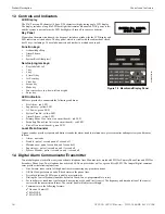
2.4.3 Relays - Programmable
The GF505 and GF510 control panels provide a factory default programmed alarm relay, fail-safe trouble relay and supervisory relay.
Each relay can be programmed to activate for other conditions (refer to “Relays” on page 59). Each Form-C relay is rated for 2 amps @
30VDC (resistive) and 0.5 amps @ 30 VAC (resistive).
Note that relay connections must be power-limited.
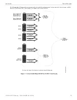
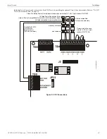
2.4.4 Remote Synchronization Output
Synchronization is a feature that controls the activation of notification appliances in such a way that all devices will turn on and off at
exactly the same time. This is particularly critical when activating strobes which must be synchronized to avoid random activation and a
potential hazard to individuals. Devices connected directly to the control panel’s NAC can be synchronized as described in “Synchro-
nized NAC Operation” on page 57.
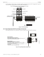
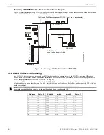
Notification appliances connected to remote power sources may require synchronization with the FACP’s devices. For the GF505 &
GF510, the Remote Sync Output is not required. Synchronization for remote power supplies is provided directly from NAC1 (Out 1).
Note that NAC 1 (Out 1) must be programmed for sync operation when used for this purpose.
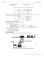
The Remote Synchronization Output is power-limited and supervised and requires a 4.7K
Ω
ELR resistor at the remote power supply end
of the wiring.
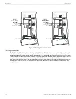
Figure 2.9 Relay Terminals
Note:
Relay contacts are shown with
power applied to the panel and no active
troubles, alarms or supervisories.
The Trouble Relay is a fail-safe relay
which will transfer on any trouble or total
power failure.
m
s10
ud
re
la
y.w
m
f
Remote Power Supply
FACP main circuit board
4.7K
Ω
ELR
Sync Input
Remote Sync Output
Figure 2.10 Remote Sync Output
2
6
GF505 & GF510 Manual —
P/N
53164
:B5 6/12/2018