


Wire Requirements
GF-510 NAC Wiring
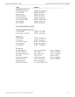
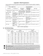
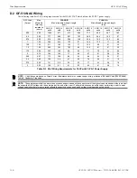
D.2 GF-510 NAC Wiring
The following table lists NAC wiring requirements for the GF-505 FACP which utilizes the FLPS-7 power supply.
NAC Load
(Amps)
Max.
allowable
total loop
resistance
(ohms)
CLASS-B
Max. allowable wire pair length
(feet)
CLASS-A
Max. allowable wire pair length
(feet)
AWG 12
solid
AWG 14
solid
AWG 16
solid
AWG 18
solid
AWG 12
solid
AWG 14
solid
AWG 16
solid
AWG 18
solid
0.25
6.00
1554
977
613
386
777
489
307
193
0.5
3.00
777
489
307
193
389
244
153
97
0.75
2.00
518
326
204
129
259
163
102
64
1
1.50
389
244
153
97
194
122
77
48
1.25
1.20
311
195
123
77
155
98
61
39
1.5
1.00
259
163
102
64
130
81
51
32
1.75
0.86
222
140
88
55
111
70
44
28
2
0.75
194
122
77
48
97
61
38
24
2.25
0.67
173
109
68
43
86
54
34
21
2.5
0.60
155
98
61
39
78
49
31
19
2.75
0.55
141
89
56
35
71
44
28
18
3
0.50
130
81
51
32
65
41
26
16
Table D.3 NAC Wiring Requirements for FACP with FLPS-7 Power Supply
NOTE:
Calculations are based on Direct-Current Resistance data for uncoated copper wire, per National Electrical Code (2005 Edition)
Table 8, Conductor Properties.
NOTE:
These distances reflect the worst case scenario and are based on the current draw of the highest candela strobes at the low end of
the supported NAC voltage with the entire load at the end of the circuit. Further distances can be achieved by performing a point to point
voltage calculation that more accurately reflects the specific devices used and how they are dispersed on the circuit.
116
GF505 & GF510 Manual —
P/N
53164
:B5 6/12/2018