


Installation
Output Circuits
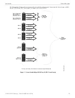
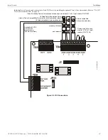
Combination Waterflow/Supervisory Zone
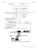
A combination Waterflow/Supervisory circuit allows an FACP to distinguish between an Alarm switch (waterflow device) and a Super-
visory switch (tamper) installed on the same circuit. Any circuit can be programmed as a Combo Type zone. The following figure illus-
trates the wiring of Zone 2 as a Style B (Class B) Waterflow/Supervisory circuit.
Requirements for the Combination Waterflow/Supervisory circuit are as follows:
The Waterflow Alarm Switch must connect to the FACP Initiating Device Circuit before the In-Line Resistor as shown in Figure
The Supervisory Switch must connect to the FACP Initiating Device Circuit after the In-Line Resistor as shown in Figure 2.6
Program the FACP Initiating Device Circuit as a Combination circuit as described in “Input Zones” on page 46.
Note that since
a Waterflow Supervisory Switch is included in a Combination circuit, the waterflow delay must be taken into consideration.
Refer to “Waterflow Delay” on page 60.
Waterflow Alarm Switch activation causes the panel to latch into alarm until the alarm condition is cleared and the FACP is reset
Supervisory Switch activation causes the panel to latch the supervisory condition if the Combo type code is selected or track (the
panel will clear when the supervisory condition is cleared) if the Combo Autoresettable Supervisory type code is selected
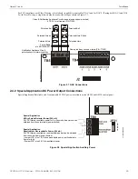
2.4 Output Circuits
2.4.1 Notification Appliance Circuits
Total current drawn from the four Style Y (Class B) Notification Appliance Circuits as well as other DC power outputs cannot exceed
7.0 amps for the GF505 & GF510 [3.0 amps maximum per NAC] powered by the FLPS-7 power supply (refer to “Power Supply Calcu-
lations” on page 100). Each circuit is supervised, power-limited and provides special application power. Refer to the Gamewell-FCI
Device Compatibility Document for a listing of compatible notification appliances.
The NACs can be converted to Style Z (Class A) by installing the optional Class A Converter module. Refer to “CAC-5X Class A Con-
verter Module” on page 29.
Class B Initiating Device Circuits (supervised and power-limited)
4.7 K
Ω
, ½ watt resistor P/N:71252
In-Line-Resistor
1.2 K
Ω
, ½ watt resistor P/N: 75579
Alarm Switch
(waterflow)
Dummy load all unused
circuits - 4.7 K
Ω
, ½ watt
resistor (P/N: 71245)
Figure 2.6 Style B Combination Circuit on Zone 2
Supervisory Switch
(tamper)
m
s10
ud
com
bo
IDC.wmf
2
4
GF505 & GF510 Manual —
P/N
53164
:B5 6/12/2018


