


Excel 800
Description of the I/O Modules
61
EN1B-0375GE51
R0910
Mixed Panel Bus I/O Modules
Features
Type: XF830A and XFU830A Mixed Panel Bus I/O
Modules
Housing: light-gray
In the event of communication problems, the relay outputs
will move to the safety positions you have configured in
CARE, see relay output point description in the CARE –
User Guide, EN2B-0182GE51 / 74-5587.
AI5
AI1 AI2 AI3 AI4
41
G1 G2
42
17
13 14 15 16
18 19 20
AI6 AI7 AI8
AO5
25
21 22 23 24
26 27 28
35
29 30 31 32 33 34
36 37 38 39 40
AO1 AO2 AO3 AO4 NO1 NO2 NO3 NO4 NO5 NO6
AO6 AO7 AO8
IN1 IN2 IN3 IN4 IN5 IN6
1 2 3 4 5 6
25 26 27 28 35 36 37 38 39 40
1
21 22 23 24 29 30 31 32 33 34
2 3
4 5 6 13 14 15 16
41 42
7 8 9
10 11 12 17 18 19 20
Analog Inputs
Analog Outputs
GND
DO
Honeywell
!
XF830A
12 BI / 8 AI / 8 AO / 6 RO
24V, 15VA, T50
0706AX0001-XFU830A
Made in Germany
0532
8
A1 A2 A3 A4 A5 A6 A7 A8 A9
B1 B2 B3 B4 B5 B6 B7 B8 B9
1
A1 A2 A3 A4 A5 A6 A7 A8 A9
B1 B2 B3 B4 B5 B6 B7 B8 B9
2
A1 A2 A3 A4 A5 A6 A7 A8 A9
B1 B2 B3 B4 B5 B6 B7 B8 B9
3
24V Relays
2
1
0
F E
D
C
B
9
8
7
6
5
4
3
A
40
External
24V for relay 1...5
24V
J1
J2
J3
J4
J5
71
75
76
77
78
COM a
COM b
24V~
24V~0
COM a
COM b
24V~
24V~0
72
73
74
S2
A1 B1 A2 B2 A3 B3 A4 B4 G1
G2
A5 B5 A6 B6 A7 B7 A8 B8
4
B7
B1 B2 B3 B4 B5 B6
B8 B9 B10 B11 B12
DI
Binary Inputs
Install. Instr.
EN1B-0375GE51
7
1
2
3
4
5
6
8
9
10 11 12
1 2 3 4 5 6 7 8 9
10 11 12
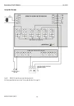
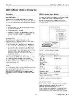
Fig. 86
XF830A Mixed I/O Module (shown with aux.
terminal packages)
B7
B1 B2 B3 B4 B5 B6
B8 B9 B10 B11 B12 AI5
AI1 AI2 AI3 AI4
41
G1 G2
42
17
13 14 15 16
18 19 20
AI6 AI7 AI8
AO5
25
21 22 23 24
26 27 28
35
29 30 31 32 33 34
36 37 38 39 40
AO1 AO2 AO3 AO4 NO1 NO2 NO3 NO4 NO5 NO6
AO6 AO7 AO8
IN1 IN2 IN3 IN4 IN5 IN6
1 2 3 4 5 6
7
25 26 27 28 35 36 37 38 39 40
1
21 22 23 24 29 30 31 32 33 34
8
2
9
3
10
4
11
5
12
6
17
13
18
14
19
15
20
16
41 42
DI
Binary Inputs
Analog Inputs
Analog Outputs
GND
DO
Honeywell
!
Install. Instr.
EN1B-0375GE51
XFU830A
12 BI / 8 AI / 8 AO / 6 RO
24V, 15VA, T50
0706AX0001-XFU830A
Made in Germany
0532
8
2
1
0
F
E
D
C
B
9
8
7
6
5
4
3
A
40
External
24V for relay 1...5
24V
J1
J2
J3
J4
J5
71
75
76
77
78
COM a
COM b
24V~
24V~0
COM a
COM b
24V~
24V~0
72
73
74
S2
24V Relays
1
2
3
4
7
1
2
3
4
5
6
8
9
10 11 12
1 2 3 4 5 6 7 8 9
10 11 12
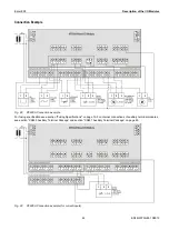
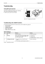
Fig. 87
XFU830A Mixed I/O Module
Legend
1 Hex switch S2
2 Status LEDs
3 Service LED
4 Power LED
Functionality of service LED and power LED: see Table 77
to Table 79 on page 77.
WARNING
Risk of electric shock or equipment damage!
It is not permitted to wire the relays of the mixed Panel
Bus I/O modules for anything other than low voltage.
Permissible Loads
load
min. load
per mixed
Panel Bus I/O
module (total
for all relay
contacts)
24 VDC/VAC
max. 3 A resistive or induc-
tive, cos
φ
≥
0.6,
no capacitive load
–
per normally
open contact
24 VDC/VAC
min. 0.05 A resistive or
inductive, cos
φ
≥
0.6,
max. 0.5 A resistive or
inductive, cos
φ
≥
0.6,
no capacitive load
>50 mW
Table 60 Permissible loads of mixed Panel Bus I/O
modules
Note
Panel Bus I/O modules feature watchdog functionality. Con-
sequently, if the module’s firmware stops running (due, e.g.,
to updating), the watchdog will switch OFF the module’s
outputs – even if the corresponding manual overrides (if
present) have been set to ON. Thus, the manual overrides
should NOT be thought of as emergency overrides; rather,
they are subordinate to the given Panel Bus I/O module’s
processor and firmware.


