


Excel 800
Description of the I/O Modules
45
EN1B-0375GE51
R0910
Technical Data
Voltage rating
0(2)…11 V (default)
Current rating
max. ±1 mA
Resolution
8 bit
Accuracy
±150 mV
Zero output voltage
< 200 mV
Protection
Short-circuit protected;
protected against failure
voltage (24 VAC, 40 VDC)
Feedback signal
automatic/manual mode and
output value
Table 48 Analog output modules data
Status LED Behavior
Automatic mode
Brightness is proportional to the
commanded output signal
Override mode
Flashes
Table 49 Analog output status LED behavior
Status LEDs with Manual Overrides
1
2
3
4
5
6
7
8
Honeywell
AUTO
0
!
100
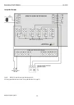
Fig. 68. Manual overrides (rotary knobs)
The XFR822/XFLR822 Analog Output Modules are
equipped with manual overrides: one for each analog
output. These rotary knobs can be manually set to either
"AUTO" or "0…100%" (infinitely adjustable).
NOTICE
Damage to the electronic module!
►
Do not use a tool to adjust the rotary knobs.
►
Do not use excessive force. Adjust only by hand.
Manual Override in the AUTO Position
When a manual override of the XFR822/XFLR822 is set to
AUTO, and the corresponding analog output has been
configured, the following applies:
If the L
ON
W
ORKS
network is functioning properly, the
output voltage of the analog output will be as
commanded.
If the L
ON
W
ORKS
network is not functioning properly, the
output voltage of the analog output will be the safety
position value.
The brightness of the status LED (red) of the analog
output will be proportional to the commanded output
signal.
When a manual override of the XFR822/XFLR822 is set to
AUTO, and the corresponding analog output has
not
been
configured, the following applies:
Regardless as to whether the L
ON
W
ORKS
network is
functioning properly or not, the output voltage of the
analog output will be 0 V (values from the L
ON
W
ORKS
Bus will be ignored, and there will be no heartbeat or
safety position).
The feedback signal on the L
ON
W
ORKS
network
nvoAoActPosnFb[ ] will have a value of 0% and a state
of 0.
The analog output status LED will be unlit.
Manual Override in the Override Position (0…100%)
When a manual override of the XFR822/XFLR822 is set to
0…100%, and the corresponding analog output has been
configured, the following applies:
The output voltage of the analog output will be 0…10 V
(direct) or 10…0 V (reverse).
The feedback signal on the L
ON
W
ORKS
network
nvoAoActPosnFb[ ] will have a value of 0…100% and a
state of -1.
The status LED (red) of the analog output will flash to
indicate “manual override.”
When a manual override of the XFR822/XFLR822 is set to
0…100%, and the corresponding analog output has
not
been configured, the following applies:
The output voltage of the analog output will be 0…10 V.
The feedback signal on the L
ON
W
ORKS
network
nvoAoActPosnFb[ ] will have a value of 0…100% and a
state of -1.
The status LED (red) of the analog output will flash to
indicate “manual override.”
Note
Panel Bus I/O modules feature watchdog functionality. Con-
sequently, if the module’s firmware stops running (due, e.g.,
to updating), the watchdog will switch OFF the module’s
outputs – even if the corresponding manual overrides (if
present) have been set to ON. Thus, the manual overrides
should NOT be thought of as emergency overrides; rather,
they are subordinate to the given Panel Bus I/O module’s
processor and firmware.
Analog Outputs Configured as Binary Outputs
Using CARE, the analog outputs can be configured
individually as binary outputs. The voltage output is then 0 V
or 10 V, depending upon the signal from the controller.


