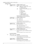
7845GSM/7845GSMCN Installation and Setup Guide
5-4
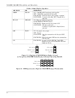
Press the [backspace] key to go to the previous field.
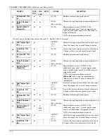
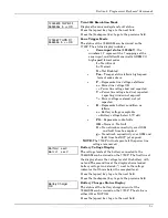
Line Voltage
xx.xxV
Line Voltage Display
The line voltage of the 7845GSM can be viewed on the
7720P. An asterisk (*) next to the voltage indicates that
this is below the accepted level.
Press the [space] key to go back to the System Status
Display.
Press the [backspace] key to go to the previous field.
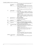
[T]
Test Msg Sent
Test Alarm
Sends a Test alarm to AlarmNet. Functional for a
registered
7845GSM only. If the device is not registered,
a message is displayed indicating that the command
cannot be executed.
NOTE:
If two CSIP’s are used, test alarms are sent to
each
central station. In addition, if the primary fails to
report, a second (backup) message is sent to the
secondary station.
[X]
Reset CPU Y/N
Reset the 7845GSM.
Pressing [N] returns to normal mode.
Pressing [Y] resets the device.
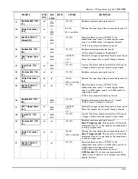
[
↑↑↑↑
]
(UP arrow)
Registering …
Registration
Registers a programmed 7845GSM with AlarmNet
.
[
↓↓↓↓
]
(DN arrow)
Enter PIN#
Registration with PIN for Replacement Module
Registers a replacement 7845GSM with AlarmNet, once
programmed, using the existing PIN #.
Force Upload of Configuration File to Server
Pressing [Y] will force the device to upload its entire
configuration file to the server.
Pressing [N] cancels the operation.
NOTE:
If the GSM module is not initialized when you
enter this command, the following screen will be
displayed:
Cannot Upload
Try Later! _
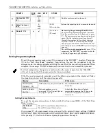
[0]
Force Server Update?
Y/N
Wait for the RSSI LEDs to light, indicating the GSM
module has completed its initialization, and try again.
[ENTER]
Strt Prog Mode?
Y/N_
Enter Program Mode
Press [Y] to enter program mode; otherwise, press [N].
WWW.DIYALARMFORUM.COM
WWW.DIYALARMFORUM.COM

