


Mounting and Wiring the Control
2-7
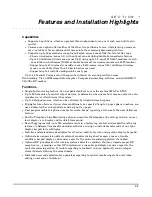
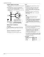
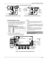
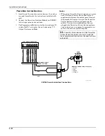
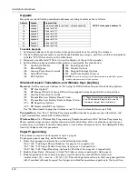
Figure 7. 4-Wire Smoke Detector Connections
+
+
2000
OHMS
EOLR
HEAT
DETECTOR
RED
EOL
POWER
SUPERVISION
RELAY MODULE
A77-716B.
USE N.O.
CONTACT,
WHICH CLOSES
WHEN POWER
IS APPLIED.
VIOLET
AUX PWR
OUTPUT
TERMINALS
5
4
_
_
+
_
BLK
_
+
4_wiresmk-007-V0
TO ZONE TERM. ( )
TO ZONE TERM. ( )
RELAY
CONTACT OPENS
MOMENTARILY UPON
FIRE ALARM RESET
PROGRAM
RELAY
AS ZONE
TYPE 54
(FIRE ZONE
RESET)
4-WIRE SMOKE
OR COMBUSTION
DETECTOR
N.C.
N.O.
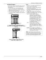
+
2000
OHMS
EOLR
HEAT
DETECTOR
RED
VIOLET
AUX PWR
5
_
+
_
BLK
_
+
4_wiresmk-008-V0
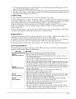
4-WIRE SMOKE
OR COMBUSTION
DETECTOR
( )
( )
+
_
TO ZONE TERM. ( )
TO ZONE TERM. ( )
TO OUTPUT 17
PROGRAM OUTPUT 17
FOR "OUT NORM
LOW" = YES IN 79 MENU
MODE AND AS ZONE
TYPE 54 IN
80 MENU MODE
EOL
POWER
SUPERVISION
RELAY MODULE
A77-716B.
USE N.O.
CONTACT,
WHICH CLOSES
WHEN POWER
IS APPLIED.
N.O.
4-Wire Smoke Detector Using Relay for Power Reset
4-Wire Smoke Detector Using Output 17 for Power Reset
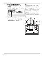
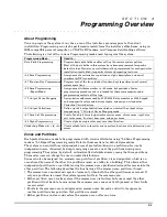
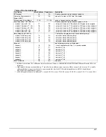
4219/4229 Expansion Zones
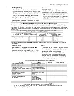
1. Connect each module to the control’s keypad terminals.
2. Assign each module a unique device address (07-11)
using its DIP switches. Device addresses determine
the zone numbers being used, as shown in the
following table.
Expander Module Addresses
For Zones… Set Module to Device Address…
09-16
07
(not available if zone-doubling enabled)
17-24
08
25-32
09
33-40
10
41-48
11
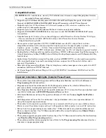
3. Connect sensors to the module’s loops.
4. If using relays with the 4229, connect the desired
field wiring to the unit's relay contact terminals.
Notes
•
Supports up to 40 expansion zones (NO or NC)
using 4219/4229 Zone Expander Modules as
follows:
•
Use 1000 ohm end-of-line resistors at the end of
loops connected to the 4219/4229 modules. (End-
of line resistors used on the control terminals are
2000 ohms.)
•
Expansion zones have normal response time
(400–500 msec), except zone connected to each
module’s loop “A,” which can be set for fast
response† (10–15 msec).
† Do not use fast response in Western Europe;
fast response is not permitted by
EN50131-1/prEN50131-3
.
BRN
GRN
BLK
(–) GROUND
RED
(+) 12VDC
YEL
4
3
2
1
ZONES
A
B
C D
F
G
H
DIP SWITCH
FOR SETTING ADDRESS
AND ZONE "A" RESPONSE
TAMPER JUMPER POSITION
4229 IN CABINET
(NOT TAMPER)
4229 REMOTE
(TAMPER PROTECTED)
TB1
4229
TB2
WHT
GR
Y
VIO
BLK
YEL
ORG
NO
NC
C
GND
NO
NC
C
RLY
1
RLY
2
RELAYS OFF
RELAY
CONNECTOR
RELAY
2
RELAY
1
(TERM 6)
(TERM 4)
(TERM 5)
(TERM 7)
NO C NC
TERMINALS ON
CONTROL PANEL
1
2
3
4
DATA OUT (>)
TO CONTROL
DATA IN (<)
FROM
CONTROL
5
8
11
REED
(TAMPER)
SWITCH
2
E
1
3
4
6
7
9
10
12
TERMINATE EACH
PROGRAMMED ZONE
WITH 1000 OHM (1K)
END-OF-LINE RESISTOR
(EACH ZONE'S MAX.
LOOP RESISTANCE
300 OHMS + EOL)
4-PIN CONSOLE PLUG
EITHER OR BOTH CAN BE USED
4229-002-V0
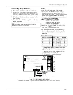
Figure 8. Wiring Connections, 4219 & 4229 (4229 shown)
Содержание ADEMCO VISTA-48D
Страница 2: ...ii ...
Страница 28: ...Installation Instructions 3 8 ...
Страница 42: ...Installation Instructions 4 14 ...
Страница 62: ...Installation Instructions 5 20 ...