


Mounting and Wiring the Control
2-5
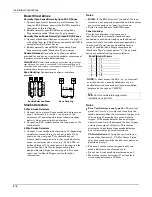
Backup Battery
1. Place the 12-volt backup battery in the cabinet.
2. After all connections to the control are completed and
AC mains power has been applied, connect the red and
black flying leads on the control board to the battery.
Do not attach these leads to the battery terminals
until all connections are completed.
Battery Saver Feature:
The battery will disconnect
from the system after its voltage decreases below 9VDC.
This assists the control panel in recharging the battery
when AC is restored.
Notes
IMPORTANT:
The panel will not power up
initially on battery power only. You must plug the
transformer in first, and then connect the battery.
UL
For UL installations and Residential fire
installations, refer to the chart below for the correct
battery size required to meet the mandatory
standby time.
UL RESIDENTIAL FIRE 24-HOUR BATTERY BACKUP REQUIREMENTS
UL has regulations which requires that all residential fire alarm control panels must be provided with a backup battery which
has sufficient capacity to operate the panel and its attached peripheral devices for 24 hours in the intended standby condition,
followed by at least 4 minutes in the intended fire alarm signaling condition. This control panel can meet these requirements
without using a supplementary power supply, provided that the panel’s auxiliary power and bell output currents are limited as
indicated below.
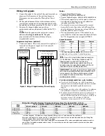
OUTPUT LIMITATIONS TO MEET CSFM 24 HOUR BATTERY BACKUP REQUIREMENTS
AND UL RESIDENTIAL FIRE INSTALLATIONS
OUTPUT CURRENT LIMITATIONS
BATTERY INFORMATION
Output Current Total
Maximum Auxiliary Current
Battery Capacity
To Use (Amp/Hrs)
Recommended Battery
(Yuasa Model No.)
600mA maximum total of
auxiliary power plus bell
output currents
45mA
160mA
200mA
425mA
500mA
4AH min.
7AH
8AH
14AH
17.2AH
NP4-12 (or ADEMCO 467)
NP7-12
NP4-12 (two) ‡
NP7-12 (two) ‡
NPG18-12
‡
NOTE:
Use two batteries, connected in parallel using Ademco Battery Harness Kit SA5140-1. (Both batteries will fit inside the
panel’s cabinet.)
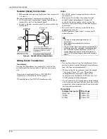
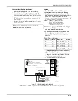
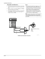
Earth Ground
Metal Cold Water Pipe or Earth Ground Rod:
Use a non-corrosive metal strap (copper is
recommended) firmly secured to the pipe/rod to which
the ground lead is electrically connected and secured.
Notes
•
This product has been designed and tested to ensure
its resistance to damage from generally expected
levels of lightning and electrical discharge, and does
not normally require an earth ground.
•
If an earth ground is desired for additional
protection in areas of severe electrical activity,
terminal 25 on the control board, or the cabinet,
may be used as the ground connection point. The
examples of good earth grounds listed at the left are
available at some installations.
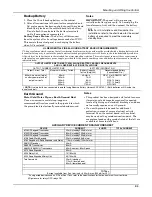
AUXILIARY DEVICE CURRENT DRAIN WORKSHEET
DEVICE
CURRENT
# UNITS
TOTAL CURRENT
6128RF Keypad/Transceiver
90mA standby/120mA alarm
6150RF Keypad/Transceiver
80mA standby/105mA alarm
6160RF Keypad/Transceiver
50mA standby/150mA alarm
6148 Fixed-Word Keypad
30mA standby/55mA alarm
6164 Keypad w/4-Zone Expander and Relay
115mA standby/190mA alarm
5881RF Receiver
35mA
5883 RF Transceiver
80mA
5882EU/5882EUH Transceivers
60mA nominal, 85mA peak
4219 Zone Expander
35mA
4204 Relay Unit
15/180mA‡
4229 Zone Expander/Relay Unit
35/100mA‡
TeleCommand
55mA (standby)
119mA (local phone)
85mA (remote phone)
*
*
TOTAL =
(Current available from Aux. terminals = 600 mA max. [500mA for UL] )
*If using wired devices such as PIRs or Dual Tecs, refer to the specifications for that particular unit's current drain.
‡Figures are for relays OFF/relays ON.
Содержание ADEMCO VISTA-48D
Страница 2: ...ii ...
Страница 28: ...Installation Instructions 3 8 ...
Страница 42: ...Installation Instructions 4 14 ...
Страница 62: ...Installation Instructions 5 20 ...