background image

Description of the device

BTS-Series | Version 3.06

9

7

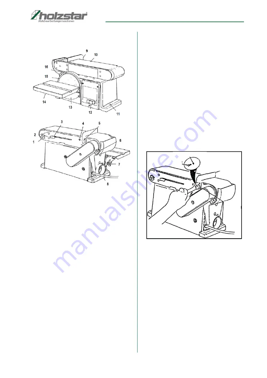
Description of the device

Fig. 3: Description

   1. Track adjustment screw

   2. Sanding belt board

   3. Tensioning lever

   4. Worktable - retaining hole

   5. Mounting hole

   6. Sanding unit - locking screw

   7. Clamping screw - table swiveling

   8. Machine foot

   9. Safety stop

10.  Grinding belt

11.  Mounting hole

12.  ON / OFF switch

13.  Sanding plate protection

14.  Worktable

15.  Grinding wheel

16.  Sanding pad

8

Assembly

Remove the machine from its packaging and remove all 
protective films. Make sure that the machine is not set up 
or put into operation in a damp or wet environment. The 
humidity should not exceed 60% and the measured 
room temperature should be between 0 ° C and 40 ° C.

For a safe footing, the machine should be mounted on a 
stable base (such as a workbench) using the holes provi-
ded in the machine base.

8.1 Safety stop

Take the safety stop as shown in Fig. 4 and fix it with the 
hexagon screw M6 x 1.0-14 and the toothed disc. When 
tightening the screw, make sure that you fasten the 
safety stop approx. 3 mm above the sanding belt. Do not 
overtighten the screw, otherwise it may over-tighten.

Fig. 4: Assembly the safety stop

     Screw

Safety
Stop

Lock washer

straddle
wrench

Содержание 5904150

Страница 1: ...BTS 150 Operating Instruction Belt and Disc sander BTS 150 BTS 250 ...

Страница 2: ...se 6 4 Technical Data 7 4 1 Type plate 7 5 Transport packaging storage 7 5 1 Delivery and transport 7 5 2 Packaging 8 5 3 Storage 8 6 Scope of delivery and Accessories 8 6 1 Scope of delivery 8 6 2 Accessories 8 7 Description of the device 9 8 Assembly 9 8 1 Safety stop 9 8 2 Working table 10 9 Settings 10 9 1 Pivoting worktable 10 9 2 Align the working table 10 9 3 Vertical grinding 11 9 4 Workta...

Страница 3: ...ways interested in valuable experience and knowledge gained from using the application which then could be shared and be valuable to develop our products even further 1 3 Limitation of liability All information and notes in these operating instructions were summarised taking the applicable standards and rules the state of the art and our long term knowledge and experiences into consideration In th...

Страница 4: ... tus of the regulations and must adapt these if nec essary The operating company must unambiguously regu late and determine the responsibilities for installa tion operation troubleshooting maintenance and cleaning The operating company must ensure that all per sons who work with machine have read and un derstood this manual Furthermore she must in struct the staff in regular intervals and inform t...

Страница 5: ...er Other personnel is not au thorized to perform these works Please contact our cus tomer service for the execution of all arising work 2 4 Personal protective equipment The personal protective equipment serves to protect per sons against impairments of safety and health while wor king The staff has to wear personal protective equip ment while performing different works on and with grind ing syste...

Страница 6: ...itable safety clothing accident prevention shoes safety glasses etc Check safety devices for correct function before starting work Read and understand safety instructions attached to the machine Perform regular maintenance Do not overload the machine If the machine is not operating normally the super visor must be informed immediately Caution is advised when people are in the work area Never chang...

Страница 7: ...se Misuse of the belt and disc sander can lead to dange rous situations Operate the belt and disc sander only in the power range specified in the technical data Never bypass or override the safety devices Never work on other materials than specified in the intended use Only operate the belt and spindle grinder in a techni cally perfect condition Never work on several workpieces at the same time Ty...

Страница 8: ... Scope of delivery Check the machine immediately after delivery for trans port damage and shortages To do this remove all indi vidual parts from the box and compare them with the fol lowing list Sanding belt grit 60 Operating instructions Suction nozzle adapter 35 to 120mm Grinding wheel grit 80 glued on 6 2 Accessories Base Item number 5914250 Abrasive sheet Ø250 K150 adhesive backed Item number ...

Страница 9: ...tive films Make sure that the machine is not set up or put into operation in a damp or wet environment The humidity should not exceed 60 and the measured room temperature should be between 0 C and 40 C For a safe footing the machine should be mounted on a stable base such as a workbench using the holes provi ded in the machine base 8 1 Safety stop Take the safety stop as shown in Fig 4 and fix it ...

Страница 10: ...ting worktable Loosen the clamping screw and bring the work table into the desired position Then tighten the clamping screw again Fig 7 Pivoting worktable 9 2 Align the working table To align the work table exactly at 90 make a right angle and hold it to the table as shown in Fig 8 Then loosen the table pivot clamping screw and align the table Finally tighten the clamping screw again Fig 8 Align t...

Страница 11: ...e the work table Loosen the two screws of the sanding guard and remove it Replace the grinding wheel with a new one and then attach the sanding guard Fig 11 Grinding wheel change 9 6 Belt change To do this loosen the tension of the sanding belt over the tensioning lever Now carefully pull off the old san ding belt Pull on the new sanding belt and align it Fi nally tighten the sanding belt over the...

Страница 12: ...witch To turn on the machine press the green switch with the sign for about one second To switch off the machine press the switch with the symbol O as shown in Fig 14 Fig 14 ON OFF Switch 10 1 Surface grinding on the sanding belt Check that the safety stop is correctly installed and tigh tened Gently press the workpiece against the sanding belt and safety stop as shown in Fig 15 with both hands Fo...

Страница 13: ...and proceed as shown in Fig 17 10 5 Grinding ends on the grinding wheel When grinding the ends of a narrow workpiece it is ea sier to use the grinding wheel with the miter fence as shown in Fig 18 Move the workpiece outward from the center to the left side of the disc Stop Workpiece Belt Table Workpiece Grinding belt Unit DANGER Always grind round parts only on the left side down side of the grind...

Страница 14: ... servicing work 12 1 Cleaning Basically the machine should be cleaned after each use When the machine is off remove the chips and dust with a broom or brush Maintenance and repair work may only be carried out by qualified personnel If the belt and disc sander does not work properly contact a dealer or our customer service The contact details can be found in chapter 1 2 Custo mer Service All protec...

Страница 15: ...elaxed Suction Check the suction daily for its adequate function If the extraction system does not work or only to a limited ex tent it must be repaired again Only then may the belt and disk grinding machine be put into operation Lubricate moving parts Lubricate the bearing points of the pulleys periodically with a high quality oil but at the latest close to about 10 operating hours Loosen the gri...

Страница 16: ...thylene PE or the upholstery parts made of polystyrene PS These substances can be reused after processing if they are passed on to a recycling center or to the disposal company responsible for them Only pass on the packaging material in such a way that it can be directly recycled Fault Possible causes Disposal Engine is not running Damaged ON OFF switch Damaged ON OFF switch lead Relay damaged Eng...

Страница 17: ...e corresponding contact data in Chapter 1 2 Customer service Indicate the following basic information for spare part orders Type of device Serial number Quantity Designation Required mode of dispatch mail freight sea air express Address of dispatch Spare part orders which do not include the above indica tions may not be taken into consideration If the indicati ons regarding the mode of dispatch ar...

Страница 18: ...Parts Drawings The following drawings is intended to help in case of service to identify necessary spare parts To order send a copy of the parts drawing with marked components to your dealer 16 1 Spare Parts Drawing BTS 150 Fig 21 Spare parts Drawing BTS 150 ...

Страница 19: ...Spare Parts Drawings BTS Series Version 3 06 19 16 2 Spare parts Drawing BTS 250 Fig 22 Spare parts Drawing BTS 250 ...

Страница 20: ...on the type plate corresponds to all the relevant provisions of the abovementioned Directive and other Directives applied below including their amendments current at the time of the declaration Relevant EU Directive 2014 30 EU EMC Directive The following harmonized standards were applied DIN EN 60204 1 2019 06 Safety of machinery Electrical equipment of machines Part 1 General requirements DIN ISO...

Страница 21: ...Notes BTS Series Version 3 06 21 18 Notes ...

Страница 22: ...www holzstar de ...

Отзывы: