9
Intructions Additionnelles - Power Clamp – ZEEWB509AP03
Pédale pour moyen de serrage power clamp
et blocage de l’arbre principale
Serrage / desserrage de roue
Additional Instruction - Power Clamp – ZEEWB509AP03
Pedal for power clamping device and main
shaft look
Clamping / unclamping the wheel
2.
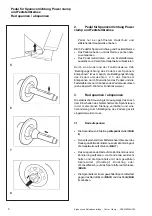
Pédale pour moyen de serrage
power clamp et blocage de l’arbre principale
Soulever la pédale seulement si le carter de roue
est ouvert et que l’arbre principal ne tourne pas.
Fig. 5 Pédale pour moyen de serrage et blocage
de l’arbre principale
•
Soulever la pédale pour serrer ou desserrer la roue.
•
Appuyer sur la pédale pour actionner le système de
blocage de l’arbre principal, donc pour immobiliser
l’arbre principal.
Par changement du mode de fonctionnement C26 ”Sens
d’actionnement de la pédale pour le serrage/
desserrage”, il est possible de renverser le sens
d’actionnement de la pédale, donc de serrer/desserrer
la roue en appuyant sur la pédale et de bloquer l’arbre
en soulevant la pédale (voir § 5. Sélection du mode de
fonctionnement).
3.
Serrage / desserrage de roue
La commande électrique est conçue telle qu’après la
mise en circuit de l’interrupteur secteur les mors de
serrage restent dans leur position instantanée et que
tout changement doit être effectué exprès par un
actionnement de la pédale.
3.1
Serrage de roue
•
Positionner les mors de serrage en position
desserrée
(
Fig. 6
).
•
Positionner le cône ou l’anneau de centrage (choisi
fonction du diamètre du trou central de la roue) sur
l’arbre principal (
Fig. 7
).
•
Placer la roue à serrer sur le cône ou l’anneau de
serrage, la maintenir, à la main, à peu près en
position verticale et pousser la douille et le moyen
de serrage (tête de serrage, anneau de serrage ou
flasque d’échange) sur le mandrin (
Fig. 8
).
•
Presser la douille et le moyen de serrage fortement
contre la roue (
Fig. 9
) et soulever la pédale (
Fig. 5
).
2.
Pedal for power clamping device
and main shaft look
Lift the pedal only when the wheel guard is open
and the main shaft does not rotate.
(Fig. 5)
Pedal for power clamping device and
main shaft lock
•
Lift the pedal so as to clamp or unclamp the wheel.
•
Depress the pedal to actuate the main shaft lock,
thus locating the main shaft.
By changing the mode of operation C26 ”Direction of
actuation of pedal for clamping/unclamping” it is
possible to reverse the direction of actuation of the pedal,
that is to clamp/unclamp the wheel by depressing the
pedal and to actuate the main shaft lock by lifting the
pedal (see § 5. Changing modes of operation).
3.
Clamping / unclamping the wheel
The electric controller is so designed that after turning
on the mains switch the clamping jaws remain in their
instantaneous position and any change must be
effected intentionally by actuating the pedal.
3.1
Clamping the wheel
•
Move the clamping jaws to
unclamped
position
(
Fig. 6
).
•
Slide the centring cone or centring ring (chosen
function of centre bore diameter of the wheel) on the
main shaft (
Fig. 7
).
•
Position the wheel to be clamped on the centring
cone or ring, hold approximately in vertical position
and slide the clamping sleeve and clamping means
(clamping head, pressure ring, or flange plate) on
the chuck (
Fig. 8
).
•
Press the clamping sleeve and clamping means
firmly against the wheel (
Fig. 9
) and lift the pedal
(
Fig. 5
).


