29
Intructions Additionnelles - Power Clamp – ZEEWB509AP03
Changement du moyen de serrage pour
les roues sans trou central
Etalonnage par l’opérateur
Additional Instruction - Power Clamp – ZEEWB509AP03
Retooling for wheels without centre bore
Readjustment by the operator
Montage du moyen de serrage power clamp
Il n’y a pas de roue sur la machine.
Remarque
Si la machine est à nouveau modifiée pour le moyen
de serrage power clamp, remettre le mode C22
(équilibreuses à affichage par LCD) à l’état 0 ou la
mode
Desserrage du moyen de serrage power
clamp bloqué
(équilibreuses à affichage par écran)
à l’état on.
Mettre les mors de serrage en position non serré.
Dévisser l’écrou conique et la garder.
Le cas échéant, enlever les moyens de serrage
spéciaux du cône de l’arbre principal.
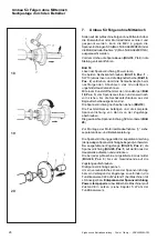
Enficher le corps de base du moyen de serrage
power clamp et visser sur la barre de traction jusqu’à
la fin du filetage ; ensuite, relâcher d’un quart de tour.
Enficher le corps de base manuellement sur le cône
et, en ce faisant, enfiler les têtes de vis dans le
disque type baïonnette.
Tourner le corps de base jusqu’à ce que le filetage
des vis colle à l’intérieur du disque type baïonnette.
Enficher la douille de serrage avec la tête de serrage
;serrer.
Serrer les vis de façon uniforme avec une clé à
fourche cote sur plats 13.
8.Etalonnage par l’opérateur
Pour l’étalonnage d’une équilibreuse p, le moyen de
serrage doit être serré sans roue.
Fixer le petit cône de centrage, le midi cône de
serrage et la douille de serrage sans tête de serrage
(
Fig. 21
) sur le mandrin.
Procéder au serrage.
Pour l’étalonnage propre, procéder comme décrit
dans le mode d’emploi de l’équilibreuse standard
relative.
Mounting the Power clamping device
There is no wheel on the machine.
Note
If the machine is retooled for the power clamping
device, reset the mode of operation C22 to status 0
(balancers with LC display) or mode
Releasing the
power clamping device is disabled
(balancers
with screen) to status on.
Move the clamping jaws to unclamped position.
Unscrew the taper nut and place aside.
Remove the special clamping means, if mounted,
from the cone of the main shaft.
Mount the basic body of the clamping device, screw
it onto the tie rod by turning it to the end of the
thread and then release it again by a quarter of a
revolution.
Slide the basic body by hand onto the cone, inserting
the screw heads through the bayonet disc.
Turn the basic body until the screw thread is
contacting the bayonet disc.
Slide on the clamping sleeve with clamping head and
clamp.
Tighten the screws evenly with an open end wrench,
width across flats 13 mm.
8.Readjustment by the operator
For readjustment of a p balancer the clamping device
must be clamped without wheel.
Fit the small centring cone, the middle centring cone
and the clamping sleeve without clamping head (
Fig.
21
) on the chuck.
Start the clamping process.
For readjustment itself proceed as specified in the
operation manual of the relative standard balancer.


