


User Manual
Installation, Assembly and Commissioning
EM1 Series AC Servo Motors
EM1-01-0-EN-2110-MA
Page
47
of
72
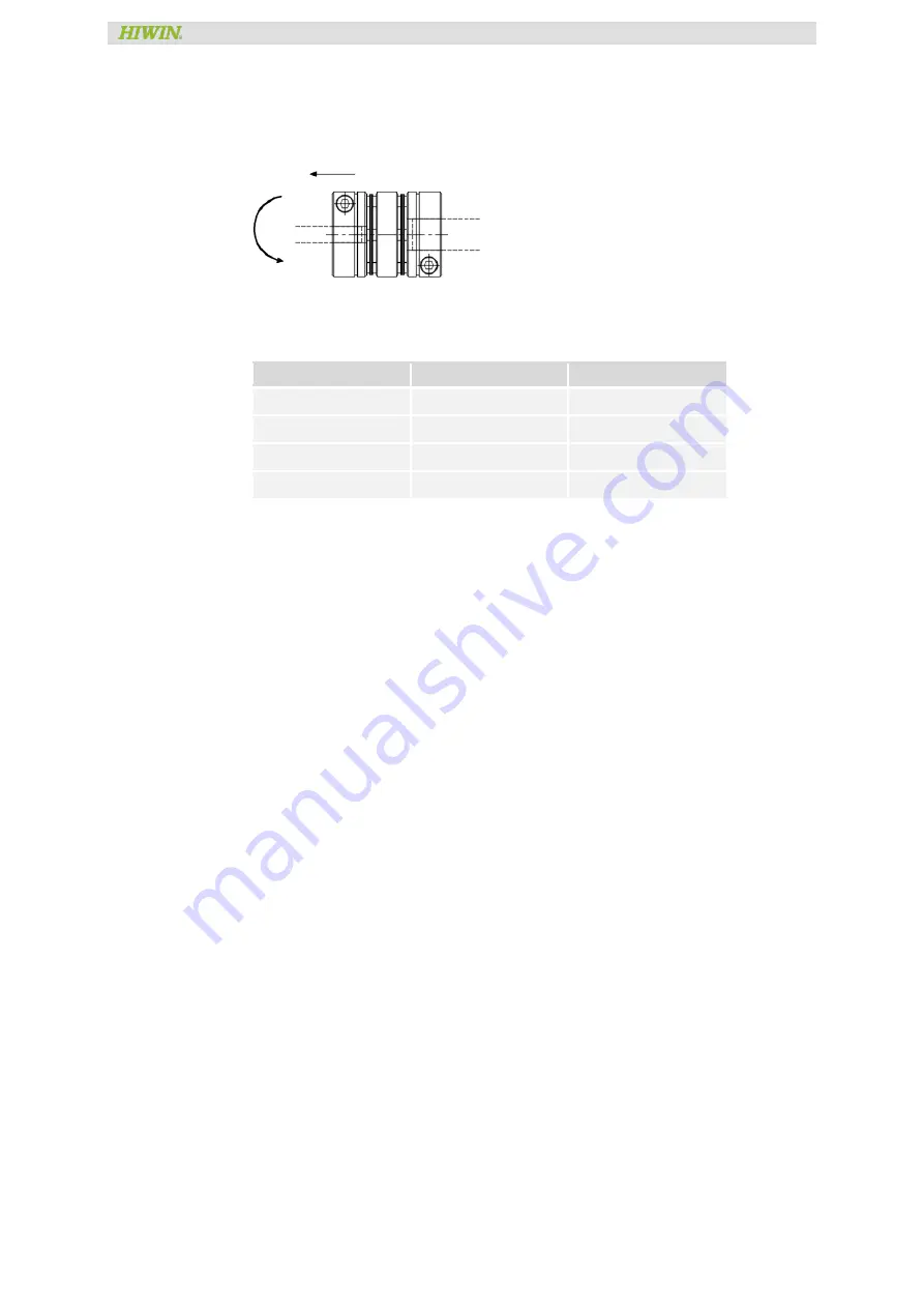
12. To check the center line of the two axes of motor shaft and coupling for easy
calibration, loosen the coupling screws on the motor shaft and load-end axis
shoulder. Rotate the coupling and see if the coupling can easily rotated along the
axial direction. To check the concentricity of both axis. Illustrations are shown below:
13. Motor Flange circle size and the PCD hole position of the flange. Please check
concentricity when installing. The size of the recommended flange installation holes
is shown in the following table.
Motor output power
Flange circle size
Tolerance
50 W ~ 100 W
30 mm
H7
200 W ~ 400 W
50 mm
H7
750 W
70 mm
H7
1 kW ~ 2 kW
110 mm
H7
14. When installing the motor flange, please make sure that the deviation between the
motor flange position hole and the load-end axis needs to be within the coupling’s
related allowable deviation.
15. If the deviation between the motor shaft and the load-end axis shoulder is too high,
and the coupling is forcefully installed, it can cause the motor shaft, coupling, or load-
end axis shoulder to break. So make sure that the deviation between the two axes is
within the coupling’s allowable deviation.
16. When choosing a coupling, we recommend choosing a flexible coupling that can
absorb the eccentricity, declination and axial direction displacement.
Axial direction


