– 84 –
(2) Overload control circuit (OVL control circuit)
●
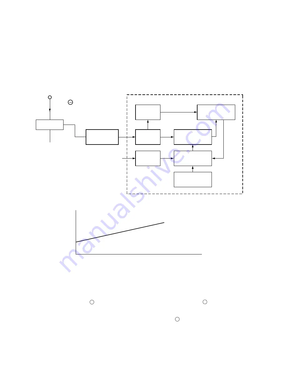
Overload control is to decrease the speed of the compressor and reduce the load when the load on the
air conditioner increases to an overload state, in order to protect the compressor, electronic components
and power breaker.
●
Overloads are judged by comparing the DC current level and set value.
●
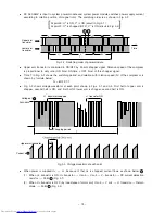
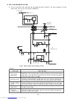
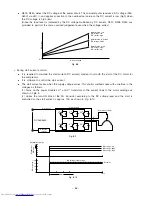
Fig. 8-4 shows the overload control system configuration and Fig. 8-5 is a characteristic diagram of
overload judgement values. There are two judgement methods-external judgement which compares the
externally set value with the DC current value regardless of the rotation speed and internal judgement
which compares the set value that varies according to the rotation speed programmed in the microcomputer
software with the DC current value.
To power module
negative terminal
(R24)
DC current
Voltage amp
circuit
(Internal judgement)
DC voltage
Judgement value according to the rotation speed
(internal judgement value)
OVL judgement
with respect to
externally set
value
A/D
converter
A/D
converter
Judgement OVL
according to the rotation
speed
Selects data according
to the rotation speed and
DC voltage
OVL start current data
Rotation speed data
Motor control
process
Microcomputer
Detection
resistor
Fig. 8-4 Overload Control System Configuration
Fig. 8-5
DC current
Rotation speed
1
. Overload external judgement circuit
●
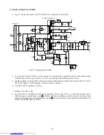
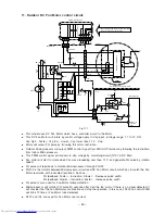
Fig. 8-1. The filter consisting of R245 and C217 removes high harmonic components from the voltage
generated by the current flowing to Detection resistor; R245 and C217 average the voltage. This voltage
is then input to IC4 pin is then amplified and supplied to microcomputer pin . The microcomputer
compares this input with the internally set value, and if the input exceeds the set value, it enters overload
control status.
●
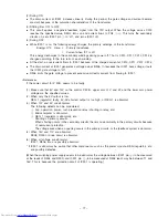
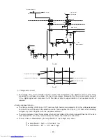
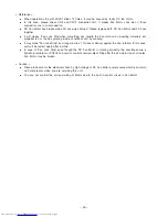
Fig. 8-7 shows the rotation speed control. When the voltage at pin of the microcomputer exceeds the
set value, the microcomputer decreases the rotation speed of the compressor and reduces the load
regardless of the rotation speed commanded by the indoor microcomputer.
5
60
60
Содержание RAC-65NH5
Страница 36: ...CIRCUIT DIAGRAM 37 ...
Страница 37: ...CIRCUIT DIAGRAM MODEL RAC 65NH5 39 ...
Страница 87: ... 99 SELF DIAGNOSIS LIGHTING MODE ...
Страница 89: ... 101 2 Outdoor unit does not operate but receives remote infrared signal ...
Страница 91: ... 103 6 Check the main P W B power circuit ...
Страница 92: ... 104 CHECKING THE REMOTE CONTROLLER ...
Страница 97: ... 109 ...
Страница 103: ... 115 PARTS LIST AND DIAGRAM INDOOR UNIT MODEL RAK 65NH5 2 1 9 7 8 6 19 20 3 11 4 5 10 13 15 14 17 16 12 22 26 18 27 ...
Страница 107: ...HITACHI PM NO 0000E Printed in Malaysia RAK 65NH5 RAC 65NH5 ...

