– 61 –
●
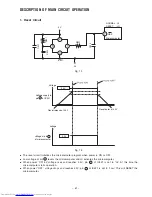
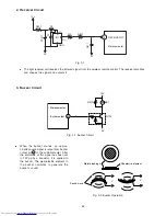
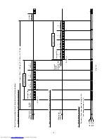
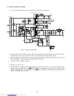
The reset circuit initializes the microcomputer program when power is ON or OFF.
●
Low voltage at pin
7
resets the microcomputer and Hi activates the microcomputer.
●
When power “ON” 5V voltage rises and reaches 4.4V, pin 1 of IC521 is set to “Hi”. At this time the
microcomputer starts operation.
●
When power “OFF” voltage drops and reaches 4.2V, pin 1 of IC521 is set to “Low”. This will RESET the
microcomputer.
DESCRIPTION OF MAIN CIRCUIT OPERATION
1. Reset Circuit
Fig. 1-1
Fig. 1-2
2
1
5
3
7
NORMAL : HI
RESET
: LO
RES
Microcomputer
C524
R521
C522
C521
R522
5V
0V
IC521
Voltage
5.0V
Reset enter at 4.2V
Reset release at 4.4V
voltage
5.0V
Voltage at pin
7
of microcomputer
Voltage supply to
pin
2
of IC521
Содержание RAC-65NH5
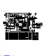
Страница 36: ...CIRCUIT DIAGRAM 37 ...
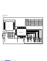
Страница 37: ...CIRCUIT DIAGRAM MODEL RAC 65NH5 39 ...
Страница 87: ... 99 SELF DIAGNOSIS LIGHTING MODE ...
Страница 89: ... 101 2 Outdoor unit does not operate but receives remote infrared signal ...
Страница 91: ... 103 6 Check the main P W B power circuit ...
Страница 92: ... 104 CHECKING THE REMOTE CONTROLLER ...
Страница 97: ... 109 ...
Страница 103: ... 115 PARTS LIST AND DIAGRAM INDOOR UNIT MODEL RAK 65NH5 2 1 9 7 8 6 19 20 3 11 4 5 10 13 15 14 17 16 12 22 26 18 27 ...
Страница 107: ...HITACHI PM NO 0000E Printed in Malaysia RAK 65NH5 RAC 65NH5 ...

