– 80 –
7. Drive Circuit
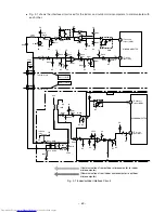
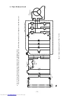
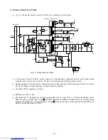
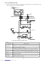
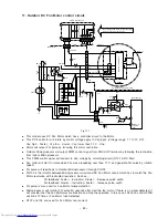
Fig. 7-1 shows the drive circuit.
The circuits for U phase, V phase and W
phase have the same Configuration.
●
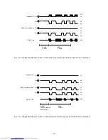
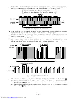
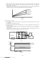
In low speed rotation mode (PWM range), as shown in Fig. 7-2, 0-5V chopper signal is ouput from microcomputer for each phase. S
ignal
output from microcomputer is ouput to IC1 and is inverted by active Lo to become 0-15V chopper signal; it is then drive the tra
nsistor
of each phase.
●
In high speed rotation mode (PWM range), as shown in Fig. 7-3, 0-5V drive signal is ouput from microcomputer for each phase (wi
th
no chopper because of full duty). Signal output from microcomputer is input to IC1 and is inverted by active Lo to become 0-15V
drive
signal; it is then drive the transistor of each phase.
Fig.. 7-1
6
5
4
3
2
1
MICR
OCOMPUTER
A
R512
R521
R511
R510
R509
R508
R507
10
9
4
3
2
1
8
7
6
5
1
13
14
15
16
17
18
1
23
11
8
7
5
4
10
6
3
9
2
3
4
5
6
7
8
9
10
11
12
13
14
15
16
17
18
19
20
21
22
23
24
25
26
27
28
19
20
21
2
3
4
5
6
7
8
9
10
12
22
B
B
B
45
44
43
42
41
38
39
40
46
IP CUTTER
Id CONTR
O
L CIRCUIT
0V
17V
R501
C404
CN14
17V
0V
PWB (MAIN)
SPM2
0V
17V
U
+
V
+
W
+
U
–
V
–
W
–
IP
Id
IC1
VCC
VCU
PGU
U
VCV
PGV
V
VCW
PGW
W
NGU
NGV
NGW
SVT
SWT
SUB
SVB
SWB
F
OC
CB
A
0
A
–
GL1
GL2
SUT
R502
R503
R504
R505
R506
Q506
R536
R535
R525
Q504
R534
Q503
R524
R533
Q502
Q501
R522
R532
R531
R526
Q505
R523
HIC
P2
N1
HIC
–
+
GR
Y
R24
U
COMPRESSOR MO
TO
R
V
W
Содержание RAC-65NH5
Страница 36: ...CIRCUIT DIAGRAM 37 ...
Страница 37: ...CIRCUIT DIAGRAM MODEL RAC 65NH5 39 ...
Страница 87: ... 99 SELF DIAGNOSIS LIGHTING MODE ...
Страница 89: ... 101 2 Outdoor unit does not operate but receives remote infrared signal ...
Страница 91: ... 103 6 Check the main P W B power circuit ...
Страница 92: ... 104 CHECKING THE REMOTE CONTROLLER ...
Страница 97: ... 109 ...
Страница 103: ... 115 PARTS LIST AND DIAGRAM INDOOR UNIT MODEL RAK 65NH5 2 1 9 7 8 6 19 20 3 11 4 5 10 13 15 14 17 16 12 22 26 18 27 ...
Страница 107: ...HITACHI PM NO 0000E Printed in Malaysia RAK 65NH5 RAC 65NH5 ...

