Chapter 4 Basic functions and System configuration
4 – 20
4.5.4 Replacement from Remote I/O MINI with mode-0
Mode-0 of remote I/O MINI is a mode that uses the remote input in 352 points (704 points in the case of using
image slots).
Transfer command (TRNS1, QTRNS1) or a handshake program was necessary in the ladder program for handing
over the data Remote I/O MINI and CPU while a lot of remote I/O numbers were able to be used.
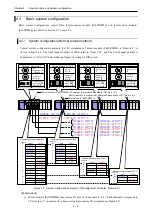
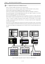
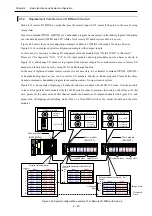
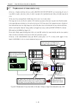
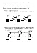
Figure 4.29 shows the system configuration example of Remote I/O MINI with mode-1 for Large H series.
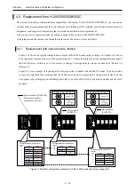
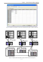
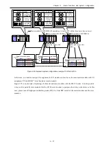
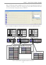
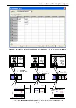
Figure 4.31 shows replaced system configuration example with compact remote.
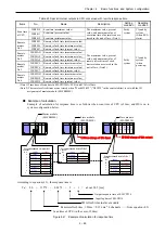
In this case, it is necessary to change I/O assignment of master module from "Word 4W/4W" to "Remote 2".
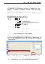
Please set I/O assignment “X16”, “Y16” for all input modules and output modules on slave bases as shown in
Figure 4.30, and change I/O numbers in program from internal outputs for communication area to remote I/O
numbers on remote slave bases by using I/O No. batch change function.
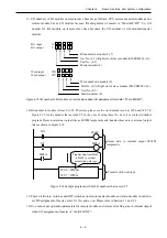
In the case of replaced compact remote system, it is not necessary to use transfer command (TRNS1, QTRNS1)
or handshake program, but you can use remote I/O numbers directly in ladder program. Please delete these
transfer command or handshake program for normal operation of compact remote system.
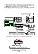
Figure 4.31 is an example of replacing all of master and slave modules with the EH-150 series. It is also possible
to leave all or partially slave modules like the H-200 series in order to postpone the wiring work of slaves. In this
case, please set the same value of first channel number and number of occupied channels with Figure 4.31, and
please turn off high-speed refreshing mode (HS) of a front DIP switch of the master module and the slave
modules.
Figure 4.29 System configuration example-13 of Remote I/O MINI with mode-0
Occupied channels of slave St.No.0
Input
Output
0
M100
~
M10F
M600
~
M60F
1
M110
~
M11F
M610
~
M61F
2
M120
~
M12F
M620
~
M62F
3
M130
~
M13F
Not used
4
M140
~
M14F
Not used
Channel
No.
Occupied channels of master
Input
Output
0
M100
~
M10F
M600
~
M60F
1
M110
~
M11F
M610
~
M61F
2
M120
~
M12F
M620
~
M62F
3
M130
~
M13F
M630
~
M63F
4
M140
~
M14F
M640
~
M64F
5
M150
~
M15F
M650
~
M65F
6
M160
~
M16F
M660
~
M66F
7
M170
~
M17F
M670
~
M67F
8
M180
~
M18F
M680
~
M68F
9
M190
~
M19F
M690
~
M69F
Channel
No.
Occupied channels of slave St. No.1
Input
Output
5
M150
~
M15F
M650
~
M65F
6
M160
~
M16F
M660
~
M66F
7
M170
~
M17F
M670
~
M67F
8
Not used
M680
~
M68F
9
Not used
M690
~
M69F
Channel
No.
Setting of slave St.No.0
0
U
First CH:
0
5
L
Number of
occupied
channels:
5
Setting of slave St. No.1
5
U
First CH:
5
5
L
Number of
occupied
channels:
5
Master module
(REM-MMH)
Slave module
(RIOH-TL)
Slave module
(RIOH-TL)
Occupied slots
Occupied slots
Setting of master
0
Operation
mode:
0
8
ON
3
4
6
7
2
1
5
Final CH:
9
X
16
X
16
Y
16
Y
16
Y
16
X
16
X
16
X
16
X
16
X
16
Y
16
Y
16
Y
16
X
16
Y
16
Y
16
Image slots
Image slots
Image slots
Occupied
slots
Occupied
slots
Содержание HIDIC EH150 EN-TRMME
Страница 9: ...MEMO ...
Страница 55: ...Chapter 4 Basic functions and System configuration 4 30 MEMO ...
Страница 69: ...Chapter 7 Daily and Periodic Inspection MEMO 7 2 ...

