Chapter 3 Name and function of each part
3 – 3
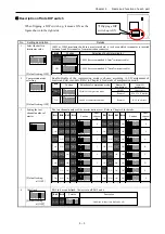
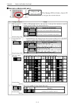
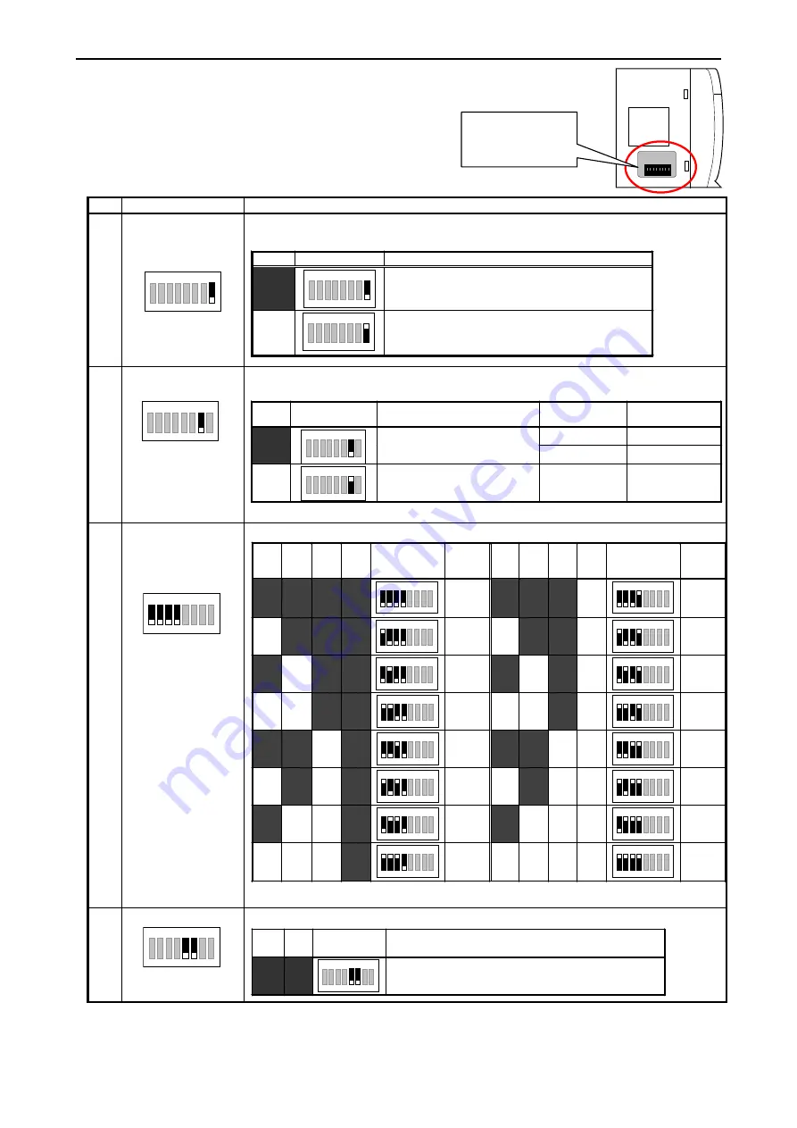
Description of Side DIP switch
No. Setting
description
Details
1
Select the built-in
terminator value
8
ON
3 4 5 6 7
2
1
[Default setting: OFF]
100
Ω
or 150
Ω
terminator build in a master module, it is chosen which terminator is inserted
between A and B terminals of communication connector.
Bit8
Position Selection
of
built-in
terminator
OFF
8
ON
3 4 5 6 7
2
1
100
Ω
(for recommended 0.3mm
2
twist-pair cable)
ON
8
ON
3 4 5 6 7
2
1
150
Ω
(for recommended 0.75mm
2
twist-pair cable)
2 Compression
mode
selecting
8
ON
3 4 5 6
7
2
1
[Default setting: OFF]
Enable/disable of the compression mode is chosen according to I/O assignment of
master and slave module. Refer to Chapter 4 for details of compression mode.
Bit7
Position
Selection of compression mode
Master I/O
assignment
Local I/O
assignment
4W/4W Unnecessary
OFF
8
ON
3 4 5 6
7
2
1
Disable of compression mode
Remote2 X16,
Y16,
Empty16
ON
8
ON
3 4 5 6
7
2
1
Enable of compression mode
Remote2
B1/1 in all slots
3 Setting
the
last
channel number of
master
8
ON
3 4
6 7
2
1
5
[Default setting:
all OFF]
The last channel number of the master station is set. Refer to Chapter 4 for details.
Bit1 Bit2 Bit3
Bit4
Position
Last
channel
No.
Bit1
Bit2
Bit3 Bit4
Position
Last
channel
No.
OFF
OFF
OFF
OFF
8
ON
3 4
6 7
2
1
5
0
OFF
OFF
OFF
ON
8
ON
3 4
6 7
2
1
5
8
ON
OFF
OFF
OFF
8
ON
3 4
6 7
2
1
5
1 ON
OFF
OFF
ON
8
ON
3 4
6 7
2
1
5
9
OFF
ON
OFF
OFF
8
ON
3 4
6 7
2
1
5
2
OFF
ON
OFF
ON
8
ON
3 4
6 7
2
1
5
A
ON
ON
OFF
OFF
8
ON
3 4
5
7
2
1
6
3 ON
ON
OFF
ON
8
ON
3 4
6 7
2
1
5
B
OFF
OFF
ON
OFF
8
ON
3 4
6 7
2
1
5
4
OFF
OFF
ON ON
8
ON
3 4
6 7
2
1
5
C
ON
OFF
ON
OFF
8
ON
3 4
6 7
2
1
5
5 ON
OFF
ON ON
8
ON
3 4
6 7
2
1
5
D
OFF
ON
ON
OFF
8
ON
3 4
6 7
2
1
5
6
OFF
ON
ON ON
8
ON
3 4
6 7
2
1
5
E
ON ON ON
OFF
8
ON
3 4
6 7
2
1
5
7 ON
ON
ON
ON
8
ON
3 4
6 7
2
1
5
F
4 Undefined
8
ON
3 4
5 6
7
2
1
[Default setting:
all OFF]
Bit 5 to 6 are undefined. Always turn off Bit 5 and 6.
Bit5 Bit6
Position Description
OFF
OFF
8
ON
3 4
5 6
7
2
1
Undefined (Always turn Bit5 and 6 off.)
When flipping a DIP switch up, it means ON as the
figure shown in the right side.
1
2
3
4
5
6
7
8
O
N
Ç
Flipping a DIP
switch up is ON.
Содержание HIDIC EH150 EN-TRMME
Страница 9: ...MEMO ...
Страница 55: ...Chapter 4 Basic functions and System configuration 4 30 MEMO ...
Страница 69: ...Chapter 7 Daily and Periodic Inspection MEMO 7 2 ...


