background image

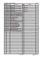
* ALTERNATIVE PARTS

--- 4 ---

ITEM

NO.

CODE NO.

DESCRIPTION

REMARKS

NO.

USED

PARTS

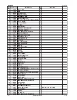
7 -- 06

DH 40MRY

102

310-123

TRANSATORY UNIT

1

103

326-485

HANDLE (A).(B) SET

1

104

991-711

DISTANCE PIECE (B)

4

105

991-690

SEAL LOCK HEX. SOCKET HD. BOLT M5X12

4

106

326-472

HOOD

1

108

307-028

TAPPING SCREW (W/FLANGE) D4X25 (BLACK)

3

109

310-124

HANDLE DAMPER

4

110

326-377

HANDLE SHAFT

1

111

326-479

HOLDER

1

112

990-941

SWITCH (B) (1P SCREW TYPE) W/O LOCK

1

113

984-750

TAPPING SCREW (W/FLANGE) D4X16

2

* 114

960-266

CORD CLIP

1

* 114

981-987Z

CORD CLIP

1

FOR SUI

115

980-063

TERMINAL

1

116

938-307

PILLAR TERMINAL

1

117

953-327

CORD ARMOR D8.8

1

* 118

500-390Z

CORD

1

* 118

500-391Z

CORD

1

FOR SUI

* 118

500-446Z

CORD

1

FOR GBR (230V)

* 118

500-454Z

CORD

1

FOR GBR (110V)

119

935-829

BRUSH CAP

2

120

999-073

CARBON BRUSH (AUTO STOP TYPE) (1 PAIR)

2

121

971-001

BRUSH HOLDER

2

122

998-471

HEX. SOCKET HD. BOLT (W/FLANGE) M5X12

1

123

326-481

HOUSING ASS’Y

1

INCLUD. 121, 124

124

938-477

HEX. SOCKET SET SCREW M5X8

2

125

326-483

TAIL COVER

1

126

302-089

TAPPING SCREW (W/FLANGE) D5X20 (BLACK)

2

127

953-174

HEX. HD. TAPPING SCREW D5X55

2

* 128

340-680C

STATOR ASS’Y 110V

1

INCLUD. 129

* 128

340-680E

STATOR ASS’Y 230V

1

INCLUD. 129

129

930-703

BRUSH TERMINAL

2

130

982-631

WASHER (A)

1

131

608-VVM

BALL BEARING 608VVC2PS2L

1

132

326-484

BEARING HOLDER

1

133

318-721

MAGNET

1

134

326-474

SPRING BASE

1

135

326-541

VINYL TUBE (I.D.9.5XT0.56X85)

1

* 136

326-490

CONTROLLER CIRCUIT 110V

1

* 136

326-491

CONTROLLER CIRCUIT 220V-240V

1

137

326-492

INTERNAL WIRE

1

138

326-488

COVER (A)

1

Содержание DH 40MRY

Страница 1: ...TECHNICAL DATA AND SERVICE MANUAL ROTARY HAMMER DH 40MRY SPECIFICATIONS AND PARTS ARE SUBJECT TO CHANGE FOR IMPROVEMENT LIST No E493 Oct 2006 D MODEL DH 40MRY Hitachi Power Tools ...

Страница 2: ...DATA AND SERVICE MANUAL symbols are used in the place of company names and model names of our competitors The symbols utilized here are as follows Symbols Utilized Competitors Company Name Model Name MAKITA HR4011C C BOSCH GBH5 40DE B ...

Страница 3: ...rison 10 6 3 Chiseling Performance Comparison 11 7 PRECAUTIONS IN SALES PROMOTION 11 7 1 Handling Instructions 11 8 REFERENCE INFORMATION 12 8 1 Grease Replacement 12 8 2 O ring Replacement 12 8 3 Structure of the Model DH 40MRY Rotary Hammer 12 9 REPAIR GUIDE 18 9 1 Disassembly 18 9 2 Reassembly 20 9 3 Screw Locking Agent TB1401 26 9 4 Tightening Torque 26 9 5 Internal Wiring 27 9 6 Insulation Te...

Страница 4: ...enforced in July 2005 The main specifications are as follows 1 Lowest vibration level in the class thanks to the dynamic damper with a leaf spring and the new vibration absorbing handle 2 High drilling speed with low vibration and noise level 3 Self drilling Good feeling 4 Constant speed with variable speed control 5 Soft touch grip for easier handling 6 Variable lock mechanism for easy working an...

Страница 5: ...ration fastest drilling speed and highest demolishing performance in this class The vibration level of the Model DH 40MRY is lowest in the class Therefore the vibration exposure limit time is longest in the class Even so the drilling speed and the demolishing performance are 10 higher than those of similar products Full load vibration level Tri axial Vibration exposure limit Maker Model Ratio of v...

Страница 6: ...zes quicker self drilling with better impact feeling Impact energy Maximum compressed air force piston force Quantity of body jumping About 5 up About 33 down About 36 down 4 2 5 Dial type constant speed with variable speed control The Model DH 40MRY is equipped with a built in electronic control circuit that can adjust the number of hammering steplessly between 1320 and 2650 min 1 with the dial E...

Страница 7: ... 5 A 230 V 4 8 A 240 V 4 6 A Motor type Insulation structure AC single phase series commutator motor Double insulation No load and full load 1 320 to 2 650 min 1 Impact rate Product 6 8 kg 15 0 lbs Excluding cord and side handle Packed 12 0 kg 26 5 lbs Weight 1 Drill bit SDS max shank 5 2 Optional Accessories 1 Drilling work for through holes Rotation and hammering Outer diameter mm 16 5 8 19 3 4 ...

Страница 8: ...ll bit SDS plus shank Code No 313465 1 Guide plate 4 Core bit shank SDS max shank 3 Core bit 2 Center pin 1 Guide plate For core bits of outer diameter 32 35 38 45 50 54 60 64 70 75 79 94 100 and 105 mm 1 1 4 1 3 8 1 1 2 1 3 4 2 2 1 8 2 3 8 2 1 2 2 3 4 2 15 16 3 1 8 3 1 16 3 15 16 and 4 1 8 Do not use the core bit whose outer diameter is 25 mm 1 or 29 mm 1 1 8 with the guide plate 2 Center pin Cod...

Страница 9: ...o 313466 For core bits of outer diameter 25 29 32 and 35 mm 1 1 1 8 1 1 4 and 1 3 8 Code No 313467 For core bits of outer diameter 38 45 50 54 60 64 70 75 79 94 100 and 105 mm 1 1 2 1 3 4 2 2 1 8 2 3 8 2 1 2 2 3 4 2 15 16 3 1 8 3 11 16 3 15 16 and 4 1 8 4 Hole drilling For drilling steel and wood 1 13 mm drill chuck 13VLD D Code No 321813 1 13 mm drill chuck 13VLD D 2 Chuck adapter SDS max shank 3...

Страница 10: ...400 mm 15 3 4 1 Bull point SDS max shank Code No 313473 313474 Overall length 280 mm 11 400 mm 15 3 4 1 Cold chisel SDS max shank 8 Cutting and stripping Asphalt cutting etc Hammering Overall length 400 mm 15 3 4 1 Cutter SDS max shank 9 Digging Substitute pick ax Hammering Code No 313476 Overall length 400 mm 15 3 4 1 Scoop SDS max shank ...

Страница 11: ...gth 220 mm 8 21 32 1 Rammer Code No 313478 2 Shank SDS max shank 12 Syringe For chip removal 500 g 1 1 lbs Can Code No 980927 70 g 2 5 oz Tube Code No 318085 320859 Syringe Bellows type Rubber ball type 13 Impact drill grease 30 g 1 oz Tube Code No 308471 Code No 981840 Note Code numbers listed above are subject to change without notice Please refer to periodic Technical News Bulletins ...

Страница 12: ...A Low vibration mechanism Full load vibration level Tri axial m sec2 Weight kg HITACHI DH 40MRY 40 1 9 16 950 10 5 240 480 1 320 2 650 105 4 1 8 480 18 29 32 260 10 15 64 104 4 7 64 90 5 82 5 8 3 6 8 15 0 lbs HITACHI DH 40MR 40 1 9 16 950 10 240 480 1 320 2 650 105 4 1 8 435 17 1 8 255 10 3 64 104 4 7 64 91 8 82 6 15 7 6 5 14 3 lbs B 40 1 9 16 1 100 8 5 160 340 1 500 3 100 105 4 1 8 460 18 7 64 26...

Страница 13: ... C B DH 40MRY DH 40MR C B DH 40MRY DH 40MR C B DH 40MRY DH 40MR C B DH 40MRY DH 40MR C B 346 251 344 302 298 197 270 266 246 171 224 232 215 171 204 200 173 121 153 155 134 96 114 117 79 56 57 68 57 53 52 55 6 2 Drilling Speed Comparison Drilling speed varies considerably depending on the work conditions Use the factory test results shown in Fig 1 for comparison purposes only Fig 1 Test conditions...

Страница 14: ...ance of the contents of the Handling Instructions and fully understands the meaning of the precautions listed on the Caution Plate attached to each tool 7 1 Handling Instructions Although every effort is made in each step of design manufacture and inspection to provide protection against safety hazards the dangers inherent in the use of any electric tool cannot be completely eliminated Accordingly...

Страница 15: ...ing portion in the speed reduction portion Special grease would leak into the motor portion and cause subsequent trouble Periodically replenish the inside of the slip clutch with Hitachi Motor Grease No 29 to full 8 2 O ring Replacement The O rings mounted on the striker and the piston are extremely important to ensure adequate sealing of the air pressure Although the O rings are made of special r...

Страница 16: ...nclined surface to absorb vibration Since the transatory unit has nonlinear spring characteristics the spring constant is lower than the conventional shearing type vibration proofing structure Thus the Model DH 40MRY can provide high vibration proofing effect with good cushioning properties The joint of the slotted groove and the cylindrical convex is provided at the center to prevent the handle f...

Страница 17: ...H 40MR in which when the drill bit or the bull point is not pressed against a concrete or similar material the second hammer moves to a position as shown in Fig 7 so that the striker is displaced from its hammering position Thus the air hole is opened and no change is caused in the air pressure chamber by the piston movement then the hammering action is stopped Striker Second hammer striker moveme...

Страница 18: ...orking tool as when the drill bit contacts steel bar wire in the concrete protecting the operator from unexpected motion of the side handle The tool inlet is covered with the front cap made of rubber to prevent chips from entering inside Two needle rollers fall into the round groove of the drill bit to retain the working tool and three key rails transmit the rotation torque To attach a working too...

Страница 19: ...s soft resin They are molded in one piece The newly designed handle and side handle structure ensures more comfortable grip for improved operability Sealing and dust proof structure The cylinder crank case section is tightly sealed with five O rings and three oil seals as shown in Fig 10 This prevents leakage of grease from the cases while also protecting them against dust from outside The tool ho...

Страница 20: ...smission of rotation In this position the tool holder grip can be manually turned and the working tool for chiseling or chipping is adjustable to the desired position in 12 steps easily Fig 13 Figure 14 is likewise a cross sectional view showing the Hammering only mode With the change lever turned another 90û the splines on the inner circumference of the lock sleeve come into mesh with the splines...

Страница 21: ... Seal Lock Hex Socket Hd Bolt M6 x 45 90 and the Seal Lock Hex Socket Hd Bolt M6 x 22 65 Remove the Gear Cover 63 from the Cylinder Crank Case 46 Remove the Bevel Pinion 48 slip clutch from the Cylinder Crank Case 46 Otherwise the Bevel Gear 32 cannot be removed later Remove the Seal Lock Hex Socket Hd Bolt M4 x 12 69 from the Change Lever 85 then remove the Change Lever 85 Remove the Retaining Ri...

Страница 22: ... removal Face the Connecting Rod 35 side of the Cylinder Crank Case 46 downward and place it on a support Press the end surface of the Crank Shaft 41 with a hand press to remove the First Gear 61 and the Crank Shaft 41 Fig 19 Clutch 31 Second Hammer 20 Cylinder Crank Case 46 Retainer Sleeve 17 Bevel Pinion 48 Cylinder 26 Cylinder Crank Case 46 Fig 18 Lock Sleeve 29 Striker 24 Fig 17 Crank Shaft 41...

Страница 23: ...g 20 Press the end surface of the bevel pinion with a hand press Bevel Pinion 48 Support Washer A 53 Spacer 58 9 2 Reassembly Reassembly can be accomplished by following the disassembly procedure in reverse However special attention should be given to the following items 1 Mounting the first gear and the crank shaft Press fit Oil Seal B 45 into the Cylinder Crank Case 46 and mount the O ring S 40 ...

Страница 24: ... Damper Washer 21 Damper 22 and Damper Holder 23 to the Retainer Sleeve 17 Mount the Damper Washer 21 aligning the R surface of the inside diameter with the R surface of the Second Hammer 20 Insert the Striker 24 into the Cylinder 26 then insert the Cylinder 26 into the Retainer Sleeve 17 Secure the Cylinder 26 and the Retainer Sleeve 17 with the four Needle Pins D6 x 6 18 and cover it with Spring...

Страница 25: ...20 Ball Bearing 6007DDUAV2S 14 Bearing Washer 15 Damper 22 Damper Holder 23 Spring Holder B 28 Clutch 31 Clutch Spring 30 Needle Pin D6 x 6 18 Striker 24 Cylinder 26 4 Mounting the fan guide Mount the Fan Guide 79 to the Housing Ass y 123 paying attention to the direction of the 0 05 convex line Fan Guide 79 Housing Ass y 123 Fig 24 0 05 convex line ...

Страница 26: ...o the Gear Holder 54 Mount the Second Gear 57 around the outer circumference of the Gear Holder 54 Before mounting apply Hitachi Motor Grease No 29 to the inner circumference of the Second Gear 57 Insert the ten Needles 56 being careful not to incline them then push in ten Springs C 55 as shown in Fig 25 Fill the slots and the through holes of the Gear Holder 54 with Hitachi Motor Grease No 29 Pre...

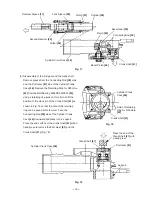
Страница 27: ... surface of the Back Cover 96 Fig 26 Handle Damper 109 Fig 26 Holder 111 Fig 27 Weight B 73 Seal Lock Hex Socket Hd Bolt M5 x 12 71 Weight A 74 Leaf Spring 66 Handle Shaft 110 Convex mark Clearance To mount Handle A B Set 103 turn the Handle Shaft 110 by about 10û and fit the Transatory Unit 102 and the Handle Shaft 110 in Handle A B Set 103 together 7 Mounting the leaf spring Sandwich the Leaf Sp...

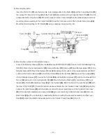
Страница 28: ...the Needle Rollers 70 and the Leaf Spring 66 is curved to the main body Apply grease to Spring Bumper B 95 and mount it to the Back Cover 96 being careful of the mounting direction To replace Rubber Sheet A 94 sufficiently degrease the adhering surface of the Back Cover 96 and adhere Rubber Sheet A 94 to the Back Cover 96 securely Mount the Back Cover 96 to the Cylinder Crank Case 46 and the Housi...

Страница 29: ... the Needle Bearing M661 62 pinion portion of the Armature Ass y 78 and Needle Roller D8 x 20 16 Fill 30 g of the Hitachi Motor Grease No 29 in the Cylinder Crank Case 46 on the First Gear 61 side and the Gear Cover 63 side 8 Oil seal and others Take care not to scratch or cut Oil Seal A 50 and Oil Seal B 45 of Cylinder Crank Case 46 Oil Seal 10 and O ring 1AS 60 9 of the Front Cover 8 O ring 1AS ...

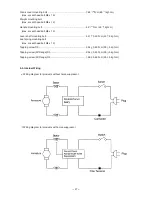
Страница 30: ... 12 Handle mounting bolt 4 9 N m 50 kgf cm Hex socket head bolt M5 x 12 Lever shaft mounting bolt 4 41 0 49 N m 45 5 kgf cm Leaf spring mounting bolt Hex socket head bolt M4 x 12 Tapping screw D5 2 94 0 49 N m 30 5 kgf cm Tapping screw W Flange D5 2 94 0 49 N m 30 5 kgf cm Tapping screw W Flange D4 1 96 0 49 N m 20 5 kgf cm 1 96 0 20 0 20 0 1 96 0 Wiring diagram for products with noise suppressor ...

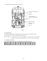
Страница 31: ...or U K products AC 2 500 V 1 minute with no abnormalities 110 V 127 V except for U K products 9 7 No load Current Values After no load operation for 30 minutes the no load current value should be as follows Voltage V Current A max 6 4 110 Mounting diagram for products with noise suppressor 5 9 120 3 2 220 3 1 230 2 9 240 Lead wires of switch and cord Control circuit ass y including noise suppresso...

Страница 32: ...min 50 Housing Ass y Stator Ass y Armature Ass y Ball Bearing 6201DD Ball Bearing 608VV Washer A Dust Washer B Bearing Holder O ring Striker O ring x 2 Piston Piston Pin Connecting Rod General Assembly Gear Cover Needle Bearing Controller Circuit Back Cover Leaf Spring Spring Bumper A Rubber Sheet B Weight B Weight A Spring Bumper B Rubber Sheet A Crank Shaft Ball Bearing 6203DD Oil Seal B O ring ...

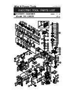
Страница 33: ...25 33 34 35 38 39 40 36 41 37 37 42 43 44 45 46 48 49 50 51 52 53 54 55 56 57 58 59 47 60 61 62 63 80 81 117 118 82 83 84 69 85 86 87 88 89 90 70 66 67 68 69 71 73 74 65 75 76 78 79 127 128 129 130 131 132 133 91 92 93 95 96 97 98 99 100 101 102 104 105 108 109 111 113 115 112 116 104 105 104 105 105 104 106 122 119 120 121 123 124 125 126 134 70 135 136 137 77 110 114 64 94 138 72 501 502 103 ...

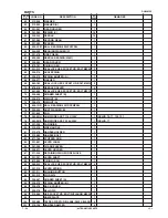
Страница 34: ...WASHER 1 22 321 289 DAMPER 1 23 321 290 DAMPER HOLDER 1 24 326 373 STRIKER 1 25 986 104 O RING 2 26 326 372 CYLINDER 1 27 326 470 LOCK SPRING 1 28 321 293 SPRING HOLDER B 1 29 321 299 LOCK SLEEVE 1 30 326 469 CLUTCH SPRING 1 31 321 295 CLUTCH 1 32 321 296 BEVEL GEAR 1 33 980 708 PISTON PIN 1 34 326 369 PISTON 1 35 326 370 CONNECTING ROD 1 36 939 540 RETAINING RING FOR D10 SHAFT 10 PCS 1 37 944 109...

Страница 35: ...326 476 WEIGHT B 1 74 326 475 WEIGHT A 1 75 620 1DD BALL BEARING 6201DDCMPS2L 1 76 302 429 DUST WASHER B 1 77 321 640 FAN 1 78 360 591U ARMATURE ASS Y 110V 120V 1 INCLUD 75 77 130 131 78 360 591E ARMATURE ASS Y 220V 230V 1 INCLUD 77 79 321 320 FAN GUIDE 1 80 313 078 SIDE HANDLE 1 81 313 079 HANDLE HOLDER 1 82 313 080 HANDLE BOLT 1 83 971 786 STOPPER ROD 1 84 321 867 LEVER LABEL 1 85 321 309 CHANGE...

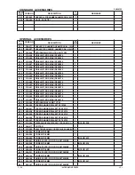
Страница 36: ...SUI 118 500 446Z CORD 1 FOR GBR 230V 118 500 454Z CORD 1 FOR GBR 110V 119 935 829 BRUSH CAP 2 120 999 073 CARBON BRUSH AUTO STOP TYPE 1 PAIR 2 121 971 001 BRUSH HOLDER 2 122 998 471 HEX SOCKET HD BOLT W FLANGE M5X12 1 123 326 481 HOUSING ASS Y 1 INCLUD 121 124 124 938 477 HEX SOCKET SET SCREW M5X8 2 125 326 483 TAIL COVER 1 126 302 089 TAPPING SCREW W FLANGE D5X20 BLACK 2 127 953 174 HEX HD TAPPIN...

Страница 37: ... 454 DRILL BIT SDS MAX D38X370 1 617 313 462 DRILL BIT SDS MAX D38X570 1 618 313 455 DRILL BIT SDS MAX D40X370 1 619 313 463 DRILL BIT SDS MAX D40X570 1 620 318 085 SYRINGE BELLOWS TYPE 1 621 944 460 TAPER SHANK DRILL BIT D11X100 1 622 944 461 TAPER SHANK DRILL BIT D12 3X110 1 623 993 038 TAPER SHANK DRILL BIT D12 7X110 1 624 944 462 TAPER SHANK DRILL BIT D14 3X110 1 625 944 500 TAPER SHANK DRILL ...

Страница 38: ...PIN B 147L FOR CORE BIT D32 35 1 653 955 165 CENTER PIN A 133L FOR CORE BIT D38 150 1 654 321 813 DRILL CHUCK 13VLD D 1 655 313 468 CHUCK ADAPTER SDS MAX 1 656 303 334 CHUCK HANDLE 1 657 930 515 CHUCK WRENCH 10G 1 658 313 469 CHEMICAL ANCHOR ADAPTER SDS MAX 12 7MM 1 659 313 470 CHEMICAL ANCHOR ADAPTER SDS MAX 19MM 1 660 313 471 BULL POINT SDS MAX 280L 1 661 313 472 BULL POINT SDS MAX 400L 1 662 31...

Страница 39: ......

Отзывы: