--- 15 ---
Tool holder
Slip clutch mechanism
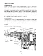
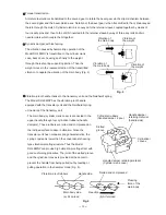
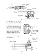
The slip clutch mechanism is described below with reference to Fig. 8. The bevel pinion and the gear holder
are coupled together by the key and press-fitting. Spring (C) and needle pins are housed in elongated grooves
of the gear holder. The needle pin is pressed against the inner face of the second gear by spring (C) to allow
idle rotation of the second gear relative to the gear holder. When an excess torque is exerted on the bevel
pinion shaft, the needle pin is raised upon the projection of the second gear against the load of spring (C) to
allow idle rotation of the second gear. With the arrangement, the clutch slips when an excessive torque is
applied to the working tool as when the drill bit contacts steel bar/wire in the concrete, protecting the operator
from unexpected motion of the side handle.
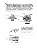
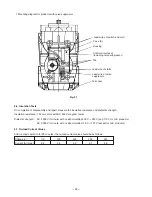
The tool inlet is covered with the front cap (made
of rubber) to prevent chips from entering inside.
Two needle rollers fall into the round groove of the
drill bit to retain the working tool, and three key
rails transmit the rotation torque. To attach a
working tool, align the groove positions turning the
working tool, then insert the working tool into the
hole until it contacts the innermost end of the hole.
Releasing the grip reverts the grip and secures the
tool in place. To remove the tool, fully pull the grip
backward and pull out the tool. (Fig. 9)
Tool
Grip
Needle roller (2 pcs.)
Key rail (3 pcs.)
Front cap
Grip
Forward Backward
Fig. 9
Fig. 8
Needle pin
Gear holder
Bevel pinion
Spring (C)
Second gear
Bevel pinion
Gear holder
Gear holder groove
Key
Cross section A-A
Содержание DH 40MRY
Страница 39: ......

