--- 24 ---
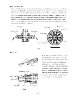
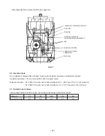
(6) Mounting the handle shaft and handle (A)
Push the Holder
[111]
in the Back Cover
[96]
by hand.
At this time, check that the clearance of the Holder
[111]
does not protrude from the main body and the Holder
[111]
does not protrude from the end surface of the
Back Cover
[96]
. Check that the convex mark of the
Back Cover
[96]
aligns with the convex mark of the
Handle Shaft
[110]
. Then mount the Handle Shaft
[110]
and push the four Handle Dampers
[109]
in the
clearances between the Holder
[111]
and the Handle
Shaft
[110]
by hand being careful not to protrude the
Handle Dampers
[109]
from the end surface of the Back
Cover
[96]
(Fig. 26).
Handle
Damper
[109]
Fig. 26
Holder
[111]
Fig. 27
Weight (B)
[73]
Seal Lock Hex. Socket
Hd. Bolt M5 x 12
[71]
Weight (A)
[74]
Leaf Spring
[66]
Handle
Shaft
[110]
Convex mark
Clearance
To mount Handle (A).(B) Set
[103]
, turn the Handle Shaft
[110]
by about 10
û
and fit the Transatory Unit
[102]
and the Handle Shaft
[110]
in Handle (A).(B) Set
[103]
together.
(7) Mounting the leaf spring
Sandwich the Leaf Spring
[66]
between Weight (A)
[74]
and Weight (B)
[73]
and fix it with the Seal Lock Hex.
Socket Hd. Bolt M5 x 12
[71]
. Sufficiently degrease the
adhering surface of Weight (B)
[73]
and adhere Rubber
Sheet (B)
[72]
securely. Be careful that the Leaf Spring
[66]
is curved to Weight (B)
[73]
. At this time, do not
misalign Weight (A)
[74]
and Weight (B)
[73]
, and do not
turn the Leaf Spring
[66]
(Fig. 27).
Rubber Sheet (B)
[72]
Содержание DH 40MRY
Страница 39: ......

