-25-
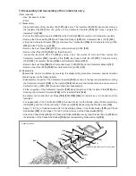
17. Disassembly and reassembly of the wheel guard
[Tools required]
• Hex. bar wrench (4 mm)
• Socket wrench (13 mm)
• Flat-blade screwdriver
• Long-nose pliers
(1) Disassembly
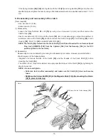
• Loosen the two Set Bolts M5 x 16
[71]
by using a hex. bar wrench (4 mm), and then remove Handle
(W)
[72]
.
• Remove the two Plates (A)
[69]
and two Dampers (A)
[70]
by using a flat-blade screwdriver.
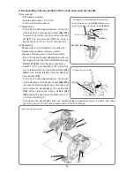
• Loosen the three Lock Nuts
[75]
and remove the Water Supply Hoses
[50] [76]
.
• Loosen the two Cap Nuts
[73]
by using a socket wrench (13 mm), and then remove Water Supply
Joint (A)
[82]
and Water Supply Joint (B)
[74]
.
(2) Reassembly
Reassembly can be conducted by reversing the disassembly procedure. However, special attention
should be given to the following items.
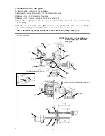
• Insert the Water Supply Hoses
[50] [76]
until they contact the end faces.
• To secure Water Supply Joint (A)
[82]
and Water Supply Joint (B)
[74]
, insert the Nozzle Bolt
[77]
into
the hole of the Wheel Guard
[80]
by using long-nose pliers and tighten the Cap Nut
[73]
from the
opposite side.
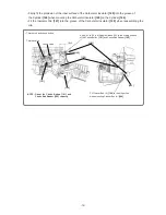
• Do not mix up the mounting positions of Handle (W)
[72]
, Water Supply Joint (A)
[82]
, Water Supply
Joint (B)
[74]
, and the Stopper Rubber
[65]
.
NOTE: Note that the Models CM 75EAP and CM 75EBP have different Stopper Rubber [65]
mounting positions.

