

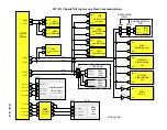

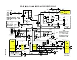


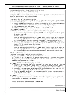
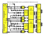

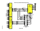


DP-4X VIDEO SIGNAL SELECTION PATH EXPLANATION
PAGE 03-02
(Continued from page 04-01)
Main Picture Outputs from I402:
Continued
Main Selected Component Out Y Pr/Pb from Pin 56 (Y), pin 54 (Pr) and pin 55 (Pb):
•
The Main Y Pr/Pb signal is then routed to the Component Selector IC
I502
. Its inputs are pin
78
(Y), pin
2
(Pr) and pin
80
(Pb). The outputs from the Component Selector IC
I502
are pin
20
(Y), pin
16
(Pr) and
pin
18
(Pb). (
For continuation see the Composite Video Signal Path 1H NTSC Circuit Diagram
)
Sub Picture Outputs from I402:
•
Selected Sub Composite (NTSC) Out from Pin 60
:
Composite Video is routed to the buffer
Q403
and then to the Composite Video Signal Path 1H Circuit.
(
See the Composite Video Signal Path 1H NTSC Circuit Diagram
)
•
Selected Sub S-Video (NTSC) Y Out from Pin 60 and S Out from pin 59
:
S-Video Y (Separate Video Y) is routed to the buffer
Q403
and then to the Composite Video Signal
Path 1H Circuit. (
See the Composite Video Signal Path 1H NTSC Circuit Diagram
)
S-Video C (Separate Video C) is routed to the buffer
Q405
and then to the Composite Video Signal Path
1H Circuit. (
See the Composite Video Signal Path 1H NTSC Circuit Diagram
)
•
Selected Sub Component Out Y Pr/Pb from Pin 60 (Y), pin 58 (Pr) and pin 59 (Pb):
The Sub Y Pr/Pb signal is then routed to the Component Selector IC
I501
. Its inputs are pin
78
(Y), pin
2
(Pr) and pin
80
(Pb). The outputs from the Component Selector IC
I502
are pin
20
(Y), pin
16
(Pr) and
pin
18
(Pb). (
For continuation see the Composite Video Signal Path 1H NTSC Circuit Diagram
)
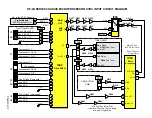
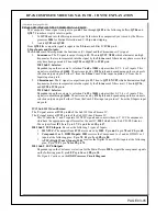
Monitor Outputs from I402:
•
Composite Monitor Output pin 52.
•
S-Out for Monitor Out
(Only when an S-In Input is being used as the Main picture)
S-Y pin
51
.
S-C pin
50
.
S-In Detection Inputs to I402:
•
When an S-In plug is inserted into the S-In jack, a mechanical switch is engaged. This notifies the Selec-
tor IC
I402
that a plug is inserted and the S-Input is forced as the selection for that input. The switch clos-
ing provides a ground or low to the detection pin.
1. S-In for
Video 3
detected by pin
2
of
I402
.
2. S-In for
Video 4
detected by pin
76
of
I402
.
3. S-In for
Video 5
is output the connector
PFS2
pin
11
and detected by pin
70
of
I402
.
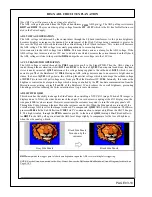
*Note: Video 2 can accept either Component and/or Composite. How this is detected is by the insertion of the Pr
plug. There’s a mechanical switch which notifies the selector IC
I402
at pin
9
. That a plug is inserted or not. This
can be helpful in troubleshooting. The Technician can use a composite input on the Y jack, insert a dummy plug
into the Pr jack and the unit will assume there’s component inputs. At this time, the On Screen display will indi-
cate Y Pr/Pb and the picture should appear but in Black and White. This can be helpful if the Technician doesn’t
have a component source at the time of troubleshooting.
Содержание 51F510
Страница 2: ...DP 4X BLANK PAGE NOTES BLANK PAGE ...
Страница 5: ...DP 4X CHASSIS INFORMATION POWER SUPPLY INFORMATION SECTION 1 ...
Страница 6: ...DP 4X BLANK PAGE NOTES BLANK PAGE ...
Страница 30: ...DP 4X BLANK PAGE NOTES BLANK PAGE ...
Страница 31: ...DP 4X CHASSIS INFORMATION MICROPROCESSOR INFORMATION SECTION 2 ...
Страница 32: ...DP 4X BLANK PAGE NOTES BLANK PAGE ...
Страница 44: ...DP 4X BLANK PAGE NOTES BLANK PAGE ...
Страница 45: ...DP 4X CHASSIS INFORMATION VIDEO INFORMATION SECTION 3 ...
Страница 46: ...DP 4X BLANK PAGE NOTES BLANK PAGE ...
Страница 61: ...DP 4X CHASSIS INFORMATION AUDIO INFORMATION SECTION 4 ...
Страница 62: ...DP 4X BLANK PAGE NOTES BLANK PAGE ...
Страница 66: ...DP 4X BLANK PAGE NOTES BLANK PAGE ...
Страница 67: ...DP 4X CHASSIS INFORMATION DEFLECTION INFORMATION SECTION 5 ...
Страница 68: ...DP 4X BLANK PAGE NOTES BLANK PAGE ...
Страница 79: ...DP 4X CHASSIS INFORMATION DIGITAL CONVERGENCE INFORMATION SECTION 6 ...
Страница 80: ...DP 4X BLANK PAGE NOTES BLANK PAGE ...
Страница 94: ...DP 4X BLANK PAGE NOTES BLANK PAGE ...
Страница 95: ...DP 4X CHASSIS INFORMATION CHASSIS PICTURES SECTION 07 ...
Страница 96: ...DP 4X BLANK PAGE NOTES BLANK PAGE ...
Страница 104: ...DP 4X BLANK PAGE NOTES BLANK PAGE ...
Страница 105: ...DP 4X CHASSIS INFORMATION DP 4X CHASSIS ADJUSTMENTS SECTION 08 ...
Страница 106: ...DP 4X BLANK PAGE NOTES BLANK PAGE ...
Страница 108: ...DP 4X BLANK PAGE NOTES BLANK PAGE ...
Страница 144: ...DP 4X BLANK PAGE NOTES BLANK PAGE ...
Страница 146: ...DP 4X BLANK PAGE NOTES BLANK PAGE ...
Страница 147: ...DP 4X CHASSIS INFORMATION SERVICE POLICY FOR THE DP 4X CHASSIS SECTION 10 ...
Страница 148: ...DP 4X BLANK PAGE NOTES BLANK PAGE ...
Страница 151: ...DP 4X BLANK PAGE NOTES BLANK PAGE ...
Страница 152: ...DP 4X BLANK PAGE NOTES BLANK PAGE ...