DP-4X MICROPROCESSOR DATA COMMUNICATIONS CIRCUIT EXPLANATION
PAGE 02-01
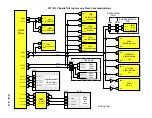
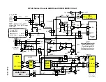
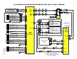
Microprocessor Data Communications circuit diagram.
(See DP-4X Microprocessor Data Communications Circuit Diagram for Details)
The Microprocessor
I004
must keep in communication with the Chassis to maintain control over the individual
circuits. Some of the circuits must return information as well so the Microprocessor will know how to respond to
different request.
The Microprocessor uses two types of communication for control, I
2
C Bus and the Serial Data, Clock and Load
lines . The I
2
C communication scheme only requires 2 lines for control. These lines are called SDA and SCL.
Serial Data and Serial Clock respectively.
Also, due to the fact that this Microprocessor operates at 3.3Vdc, it requires a Level Shift IC to bring the DC
level of the control lines up to make it compatible with the connected components. The Level Shift IC also brings
the DC levels down as outside circuits communicate with the microprocessor.
The Microprocessor communicates with the following ICs:
ON THE TUNER PWB:
•
U301 Main Tuner
•
U302 PinP Tuner
ON THE SIGNAL PWB:
•
UD2003 Digital Module
(
ATSC Tuner
)
•
UY01 Flex Converter
•
I007 and I011 EEPROM
•
I009 Level Shift
•
IA01 Audio Control
•
IV01 A/V Selector
•
IV02 3D Y/C
•
IV08 1H Main Video Chroma
•
IV12 1H Sub Video Chroma Selector
•
IY04 Rainforest (RGB Processor)
•
I501 Sub Y Pr/Pb Selector
•
I502 Main Y Pr/Pb Selector
•
I401 Audio Selector
•
I402 Video Selector
ON THE SUB DEFLECTION PWB:
•
IB01 Vertical Drive
The following explanation will deal with the communication paths used between the Microprocessor and the re-
spected ICs.
ON THE TUNER PWB:
U301 Main Tuner (with MTS outputs) and U302 Sub Tuner (mono Audio Output).
The Microprocessor
I004
controls the Tuners by
SDA2
(Data) and
SCL2
(Clock) I
2
C communication lines.
SCL2
and
SDA2
lines for the Tuners are output from the Microprocessor
I004
at pins (
31 SDA2 and 28 SCL2
)
respectively. These lines go through the connector
PTU1
pins (
10
and
9
) then directly to the Tuners,
SDA2
at pin
(
5
) and
SCL2
at pin (
4
). These lines control band switching, programmable divider set-up information, pulse
swallow tuning selection, etc...
(Continued on page 2)
Содержание 51F510
Страница 2: ...DP 4X BLANK PAGE NOTES BLANK PAGE ...
Страница 5: ...DP 4X CHASSIS INFORMATION POWER SUPPLY INFORMATION SECTION 1 ...
Страница 6: ...DP 4X BLANK PAGE NOTES BLANK PAGE ...
Страница 30: ...DP 4X BLANK PAGE NOTES BLANK PAGE ...
Страница 31: ...DP 4X CHASSIS INFORMATION MICROPROCESSOR INFORMATION SECTION 2 ...
Страница 32: ...DP 4X BLANK PAGE NOTES BLANK PAGE ...
Страница 44: ...DP 4X BLANK PAGE NOTES BLANK PAGE ...
Страница 45: ...DP 4X CHASSIS INFORMATION VIDEO INFORMATION SECTION 3 ...
Страница 46: ...DP 4X BLANK PAGE NOTES BLANK PAGE ...
Страница 61: ...DP 4X CHASSIS INFORMATION AUDIO INFORMATION SECTION 4 ...
Страница 62: ...DP 4X BLANK PAGE NOTES BLANK PAGE ...
Страница 66: ...DP 4X BLANK PAGE NOTES BLANK PAGE ...
Страница 67: ...DP 4X CHASSIS INFORMATION DEFLECTION INFORMATION SECTION 5 ...
Страница 68: ...DP 4X BLANK PAGE NOTES BLANK PAGE ...
Страница 79: ...DP 4X CHASSIS INFORMATION DIGITAL CONVERGENCE INFORMATION SECTION 6 ...
Страница 80: ...DP 4X BLANK PAGE NOTES BLANK PAGE ...
Страница 94: ...DP 4X BLANK PAGE NOTES BLANK PAGE ...
Страница 95: ...DP 4X CHASSIS INFORMATION CHASSIS PICTURES SECTION 07 ...
Страница 96: ...DP 4X BLANK PAGE NOTES BLANK PAGE ...
Страница 104: ...DP 4X BLANK PAGE NOTES BLANK PAGE ...
Страница 105: ...DP 4X CHASSIS INFORMATION DP 4X CHASSIS ADJUSTMENTS SECTION 08 ...
Страница 106: ...DP 4X BLANK PAGE NOTES BLANK PAGE ...
Страница 108: ...DP 4X BLANK PAGE NOTES BLANK PAGE ...
Страница 144: ...DP 4X BLANK PAGE NOTES BLANK PAGE ...
Страница 146: ...DP 4X BLANK PAGE NOTES BLANK PAGE ...
Страница 147: ...DP 4X CHASSIS INFORMATION SERVICE POLICY FOR THE DP 4X CHASSIS SECTION 10 ...
Страница 148: ...DP 4X BLANK PAGE NOTES BLANK PAGE ...
Страница 151: ...DP 4X BLANK PAGE NOTES BLANK PAGE ...
Страница 152: ...DP 4X BLANK PAGE NOTES BLANK PAGE ...


