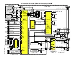
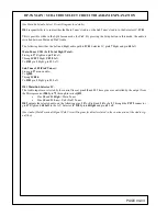
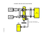

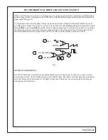
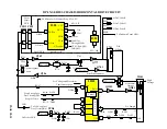
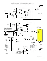
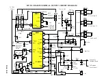
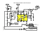

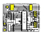


DP-3X VERTICAL OUTPUT CIRCUIT EXPLANATION
PAGE 05-07
(See the Vertical Output Circuit for details)
I601 B+:
The Vertical Output IC
I601
requires
SW+28V
to operated. This voltage is supplied from the Power Supply. The
output for the
SW+28V
pulse is from pin
15
of
T901
. This power supply is protected by
E904
, rectified by
D922
, filtered by
C933, L918, C934
and output from the
PPD5
connector pin
1
and
2
. It arrives at the Deflection
PWB and is routed through the Vertical B+ Excessive Current Sensor
R629
,
Q604
to pin
10
of
I601
.
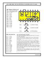
TRIGGER PULSE:
The Trigger pulse is routed from the Rainforest IC
I501
pin
35
on the Signal PWB. It is output to the
PPS3
con-
nector pin
10
, to the Power Supply PWB
PPS3
connector pin
10
to the Deflection PWB. It is then sent to the
Trigger Input on
I601
pin
3
.
During Trace, the internal Ramp Generator circuit using
C603
connected to pin
7
as the time constant begins
charging. As it charges, the Pump Up circuit is also charging from the
SW+28V
to
C605
, through pin
11
to an
internal switch of
I601.
When the Trigger pulse arrives (Retrace Time), the internal switch toggles over to the
output stage push pull pair inside
I601
, and the +28V charged capacitor
C605
discharges. The output stage push
pull pair inside
I601
already have +28V input from pin
10
. So the output pulse from pin
1
is now near 50V p/p.
This is only needed for a short duration of time, (retrace) so the Charge Pump circuit eliminates the need for a
50V power supply.
(V BLK) VERTICAL BLANKING PULSE GENERATION:
When the Charge Pump discharges and produces the 50V p/p pulse for Vertical drive during retrace, this pulse at
pin
11
is also routed as the Vertical Blanking pulse. It’s amplitude is around 21V p/p and is sent to the following
circuits;
•
Vertical Sweep Loss detection circuit
•
Convergence circuit for vertical correction waveform generation
•
To the
PPD3
,
PPS3
connector pin 12 to be sent to various circuits on the signal PWB. The Micro-
processor uses this signal to time it’s OSD.
VERTICAL OUTPUT PULSE:
The Vertical Output pulse is then routed to the Vertical Yokes generating a linear sawtooth current which moves
the beam. (Trace = from top to bottom, Retrace = from bottom to top). This linear current is generated by the
charge time constant of the vertical yokes charging
C607
through the low ohm resistors
R619
,
R620
.
VERTICAL YOKE CHARGE PULSE:
The pulse generated on the positive side of
C607
is also routed through the parabolic wave form generation cir-
cuit of
R621
and
C608
to the side pincushion circuit and to the dynamic focus circuit for corrections to deflection
and focus.
The pulse generated on the positive side of
C607
is also routed back to
I601
pin
8
and
9
. The AC component of
this signal is for vertical linearity compensation. The DC component of this signal and the DC component pro-
vided by the Vertical size pot into pin
4
are routed back to the Ramp generator circuit described above. The DC
component determines the charge time associated with the ramp generator or in other words, the Vertical height.
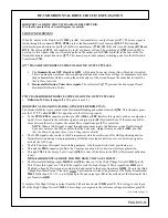
D SIZE SWITCH:
When Magic Focus is activated by either the Magic Focus button or customer’s menu or during service when the
sensors are initialized,
Q603
receives the
D Size
command from the Digital Convergence Unit,
UKDG
pin 15 of
PDS
connector. When
Q603
turns on, it bypasses
R611
and lowers the resistance from
R607
(Vertical Size Pot)
to ground. This increases the Vertical size to allow positive contact of the light pattern hitting the sensors.
Содержание 46W500
Страница 2: ...DP 3X BLANK PAGE NOTES BLANK PAGE ...
Страница 6: ...DP 3X BLANK PAGE NOTES BLANK PAGE ...
Страница 7: ...DP 3X CHASSIS INFORMATION POWER SUPPLY INFORMATION SECTION 1 ...
Страница 8: ...DP 3X BLANK PAGE NOTES BLANK PAGE ...
Страница 23: ...DP 3X CHASSIS INFORMATION MICROPROCESSOR INFORMATION SECTION 2 ...
Страница 24: ...DP 3X BLANK PAGE NOTES BLANK PAGE ...
Страница 35: ...DP 3X CHASSIS INFORMATION VIDEO INFORMATION SECTION 3 ...
Страница 36: ...DP 3X BLANK PAGE NOTES BLANK PAGE ...
Страница 50: ...DP 3X BLANK PAGE NOTES BLANK PAGE ...
Страница 51: ...DP 3X CHASSIS INFORMATION AUDIO INFORMATION SECTION 4 ...
Страница 52: ...DP 3X BLANK PAGE NOTES BLANK PAGE ...
Страница 57: ...DP 3X CHASSIS INFORMATION DEFLECTION INFORMATION SECTION 5 ...
Страница 58: ...DP 3X BLANK PAGE NOTES BLANK PAGE ...
Страница 69: ...DP 3X CHASSIS INFORMATION DIGITAL CONVERGENCE INFORMATION SECTION 6 ...
Страница 70: ...DP 3X BLANK PAGE NOTES BLANK PAGE ...
Страница 83: ...DP 3X CHASSIS INFORMATION ADJUSTMENT INFORMATION SECTION 7 ...
Страница 84: ...DP 3X BLANK PAGE NOTES BLANK PAGE ...
Страница 98: ...DP 3X BLANK PAGE NOTES BLANK PAGE ...
Страница 99: ...DP 3X CHASSIS INFORMATION MISCELLANEOUS INFORMATION SECTION 8 ...
Страница 100: ...DP 3X BLANK PAGE NOTES BLANK PAGE ...
Страница 111: ...DP 3X CHASSIS INFORMATION DP 33W 46W500 DVD PLAYER TROUBLESHOOTING SECTION 9 ...
Страница 112: ...DP 3X BLANK PAGE NOTES BLANK PAGE ...
Страница 131: ...DP 3X CHASSIS INFORMATION THINGS YOU SHOULD KNOW SECTION 10 ...
Страница 132: ...DP 3X BLANK PAGE NOTES BLANK PAGE ...
Страница 134: ...DP 3X BLANK PAGE NOTES BLANK PAGE ...
Страница 161: ...DP 3X BLANK PAGE NOTES BLANK PAGE ...
Страница 162: ...DP 3X BLANK PAGE NOTES BLANK PAGE ...


