background image

RA66

DA52

DA51

QA51

RA55

RA11

DA03

DA04

DA05

RA10

Right

Left

I001

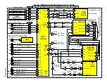
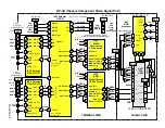
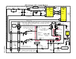
DP-3X Series Chassis AUDIO and VIDEO MUTE Circuit

Micro Processor

"SPOT"

Horizontal Sweep Loss Det.

Vertical Sweep Loss Det.

(From Deflection PWB)

IAA1

FRONT L & R

Audio Output

Mute

CAA2

4

2

R In R Out

L In L Out

CAA4

11

PAGE 02-08

7

12

Mute = Lo

49

I010

3

V MUTE

Level

Shift

17

V MUTE 1

Rec Mute

CAC5

CAC4

QA02

QA01

71

7

A MUTE

13

A MUTE

DA07

DA06

RAA4

QAA2

RAA8

RAA7

Terminal PWB

R555

C545

C546

R597

R5AD

Q525

D509

D507

8

H Blk

39

I501

Rainforest

PPS3

Q526

R598

R599

V MUTE

R5A3

R5A7

Q528

4

Spot

Q529

R5A4

HVcc 9.3V

R546

D511

C547

D510

R5A5

R5A1

Q527

V MUTE 2

CRT PWB

PSC

565

R561

D516

R5K6

Q523

FC H Blk

Q522

FC V Blk

PST1

V MUTE 1

11

8

PPD3

4

Deflection

PWB

HVcc 9.3V

NOTE: V MUTE 1 becomes

V MUTE 2 on Signal PWB 2 & 3

Then V MUTE 1 again on CRT PWB

D503

R564

Right

CA52

CA55

Left

QA54

CA51

CA54

JA01

R

L

DA53

Out To

Hi-Fi

See Sweep Loss Detection

Circuit Diagram for details

Turns on Q856

which removes

base drive for R,

G and B drivers.

Simply grounds out Audio

coming from the Monitor

Outputs.

25

A MUTE

MAIN TUNER

U301

4

PPS4

2
3

RAA2

RAA1

IA01

Ft. Audio Control

17

SPK OFF

23

8

CA19

CA06

D508

Power PWB

FBP In

70

D405

D406

38

Rec Mute To QV08, 09

DA54

DP-36 Only

All Chassis

But the DP-36

Содержание 46W500

Страница 1: ... T 2003 MODEL RELEASE DIGITAL HD READY PTV Model No Chassis 46W500 DP33W 2 51S700 DP36 1 3 57S700 DP36 1 3 65S700 DP36 1 3 51S500 DP37 3 57S500 DP37 3 65S500 DP37 3 57T500 DP37C 65T500 DP37C 57X500 DP37D 65X500 DP37D 1 Includes built in ATSC QUAM tuner 2 Includes built in DVD Player 3 Includes built in Photo Card Reader http www hitachiserviceusa com HITACHI PROJECTION TELEVISION ...

Страница 2: ...DP 3X BLANK PAGE NOTES BLANK PAGE ...

Страница 3: ...2 MICROPROCESSOR INFORMATION Microprocessor DATA COMMUNICATION Explanation 02 01 Microprocessor DATA COMMUNICATION Circuit Diagram 02 05 Audio Video Mute Circuit Diagram Explanation 02 06 Audio Video Mute Circuit Diagram 02 08 Microprocessor NTSC Sync Input Circuit Diagram Explained 02 09 Microprocessor NTSC Sync Input Circuit Diagram Circuit Diagram 02 10 SECTION 3 VIDEO CIRCUIT INFORMATION Video...

Страница 4: ...Convergence Interconnect Circuit Diagram 06 05 Remote CLU5728TSI Digital Convergence Mode Functions DP 37 06 06 Remote CLU5727TSI Digital Convergence Mode Functions DP 33W 06 07 Remote CLU5725TSI Digital Convergence Mode Functions DP 37C and DP 37D 06 08 46 Overlay Dimensions 06 09 51 Overlay Dimensions 06 10 57 Overlay Dimensions 06 11 65 Overlay Dimensions 06 12 SECTION 7 ADJUSTMENT INFORMATION ...

Страница 5: ...y Check 09 04 DVD Player Control Check 09 05 DVD Player Audio Video Check 09 06 DVD Player Interface Block Diagram 09 07 DVD Player Video Signal Diagram 09 08 DP 33W Microprocessor Data Communication Signal Diagram 09 09 DVD Player Audio Signal Path Signal Diagram 09 10 DVD PLAYER TROUBLESHOOTING PICTURES DVD Player Front View and Plastic Cover 09 11 DVD Player Control Panel Removal and Plastic Co...

Страница 6: ...DP 3X BLANK PAGE NOTES BLANK PAGE ...

Страница 7: ...DP 3X CHASSIS INFORMATION POWER SUPPLY INFORMATION SECTION 1 ...

Страница 8: ...DP 3X BLANK PAGE NOTES BLANK PAGE ...

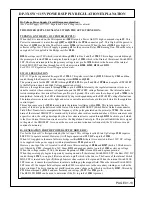
Страница 9: ...ty that the LED itself is malfunctioning If the LED turns on but then quickly goes off then the power supply that is being monitored can be sus pected ON If the LED is on then the power supply that is being monitored is working normal There is the possibility that the power supply being monitored may in fact be present but low If after making visual inspection and all seems OK but there s still a ...

Страница 10: ...he Stand By Power Supply 1 Green L E D for visual trouble sensing observation C919 GREEN L E D U901 L924 PPS5 10 8 9 SBY 5V PAGE 01 02 D913 4 Gnd Stand By DC DC Converter C918 C922 5 6 7 Gnd Gnd Gnd D913 illuminates when the Stand By 5V is available ...

Страница 11: ... the possi bility that the power supply being monitored may in fact be present but low If after making visual in spection and all seems OK but there s still a problem be sure to check the accuracy of the power supply in question RED LED D912 D912 is used to monitor the Start Up and Run voltage for the Driver IC I901 This IC is used to generate the fol lowing voltages Audio SW 30V SW 10V 220V SW 28...

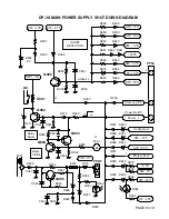
Страница 12: ...0 39 Ohm E907 D932 L923 10 R952 R953 T901 115V Over Current Q905 D912 R913 Run I901 Driver Output IC I906 AC 4 Regulator Photocoupler 3 1 2 Start Up Osc B 16 3V 4 7 5P P R907 R906 D911 C911 R918 D907 1 RED L E D From Relay S901 Hot Ground from pin 9 of T901 SW 115V GREEN L E D 1 1 00A SW 28V D954 L919 2 R964 D952 D953 See Shut Down Circuit 5 D908 D910 C924 R934 D955 C949 From Pin 8 T901 SW 115V R9...

Страница 13: ... equal value 15K One to the positive voltage SW 28V and one to the negative voltage SW 28V At their tie point neutral point the voltage is effec tually zero 0 volts If however the negative voltage is lost the neutral point will go positive This in turn will cause the zener diode D952 to fire creating a Shutdown Signal through D953 and on to the appropriate circuit indicated on the drawing on page ...

Страница 14: ...tified by D907 filtered by C911 then routed clamped by D911 and now becomes run voltage 23 3V for I901 pin 4 HOT GROUND SIDE SHUT DOWN SENSING CIRCUITS Specific to I901 In addition there are 4 Hot Ground side Shutdown inputs that are specifically detected by the main power driver IC I901 These sensors circuits protect I901 from excessive current temperature or over voltage LATCHED SHUT DOWN MONITO...

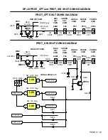
Страница 15: ...nd By 12 of the shut down inputs are not active Shorted SW 35V from voltage divider R940 and R941 off the SW 115V from pin 11 of T901 This voltage is monitored by D938 Shorted SW 10V from pin 16 of T901 This voltage is monitored by D939 Shorted SW 5 5V from pin 1 of I905 This voltage is monitored by D940 Shorted 220V from pin 10 of T901 This voltage is monitored by D941 and D942 Shorted SW 6 3V fr...

Страница 16: ...the Green CRT PWB to Signal PWB via PSC connector pin 2 called Gain Cont From the PSC connector pin 2 to the base of Q554 which inverts this High to a Low From Q554 collector to the PPS4 connector pin 5 now called Protect_SW From the Signal PWB to Power PWB via PPS4 connector pin 5 This signal would be low if the 220V draws excessive current on the Blue CRT PWB 5 of these inputs are monitoring for...

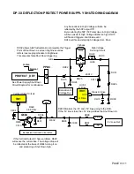
Страница 17: ...re and this high will be routed to pin 7 of IH01 This is the Horizontal Drive for High Voltage and this IC will shut off turning off High Voltage drive pulses Excessive Current Detection See DP 3X Power Supply Shut Down Circuit Diagram for details On the Power PWB SW 115V Excessive Current Detection Monitored by Q905 and D928 and routed through D930 If the Deflec tion High Voltage Circuit draws to...

Страница 18: ... D917 C921 Q902 R927 D918 D933 R929 PPS4 6 7 R949 R948 Q904 C947 Q903 C948 R950 D959 D961 D960 Audio Gnd D958 D957 SW 10V D948 D947 SW 5 5V D951 Protect_Def D950 D949 SW 7V 6 3V R937 R939 D953 D952 SW 28V R965 D954 SW 28V R964 Q905 R944 C943 D925 C949 R946 E907 PPD5 9 10 L923 D928 R951 C950 R952 D929 D931 D932 11 T901 S901 PAGE 01 10 SW 115 D941 R956 C952 A Point D930 R953 5 6 Protect_CPT 1 Power_...

Страница 19: ...n triggering Any fluctuations in High Voltage will also be reflected by the 50P output P P By monitoring the 50P 50 Pulse rises in High Voltage will be sensed If High Voltage climbs too high DH15 will fire and trigger a shut down event DH14 will fire and stop High Voltage Horz Drive If the Vertical Output IC has a problem R629 will sense the current rise The voltage drop will be reflected at the b...

Страница 20: ...V REE9 QEA8 REF6 REF5 VM Circuit 8 EGB1 2 PSC GREEN CRT PWB PPS4 SIGNAL PWB PPS4 POWER PWB 2 PSC SIGNAL PWB GAIN CONT PROT SW RED CRT PWB BLUE CRT PWB REF2 CEC1 VM Circuit RGB Drives GAIN CONT GAIN CONT GAIN CONT 5 5 C592 D404 Q554 RL50 R420 SW 3 3V I403 SW 3 3V Reg 3 SW 5 5V 1 SW 5V I402 SW 5V Reg 3 2 SW 2 2V I404 4 SW 2 2V Reg 5 SW 9V D403 SW 9 3V D401 D402 SIGNAL PWB 2 of 3 Active Lo Active Hi ...

Страница 21: ...al This action causes pin 1 of I901 to manipulate the internal oscillator within I901 This in turn causes the fre quency of the drive pulse delivered to the Gate of the internal SMOSFET Switch Metal Oxide Semiconductor Field Effect Transistor to manipulate the frequency of the pulse generated on the primary of T901 The current drain of the internal SMOSFET is monitored by four low ohm resistors me...

Страница 22: ...115V R942 R914 D926 E906 0 5K I904 3 1 2 PPD5 L923 9 10 0 86A SW 115V SW 115V 11 T901 0 39 Ohm R944 R952 R953 12 C942 C943 Q905 C949 R946 R942 D928 D932 D925 3K E907 Deflection B 115V C944 R943 X Ray Protect D931 D929 D930 8 T901 9 C914 R940 FB OCP 3 2 R912 150V From Bridge D902 F903 5A 1 2 5 6 T901 R908 R909 R910 R911 0 22 Ohm D S Cold Ground from pin 12 of T901 C905 AC for D902 Supplied from Rel...

Страница 23: ...DP 3X CHASSIS INFORMATION MICROPROCESSOR INFORMATION SECTION 2 ...

Страница 24: ...DP 3X BLANK PAGE NOTES BLANK PAGE ...

Страница 25: ... I010 Level Shift I501 Rainforest IA01 Audio Control ON THE TERMINAL PWB IY01 3D Y C IV01 A V Selector IV11 Digital to Analog Converter DAC IV03 Y Pr Pb Selector IY04 Main Video Chroma Y Pr Pb Selector IY03 Sub Video Chroma Y Pr Pb Selector The following explanation will deal with the communication paths used between the Microprocessor and the re spected ICs ON THE SIGNAL PWB UD2003 Digital Tuner ...

Страница 26: ... responsible for receiving any video input and converting it to 33 75 Khz output 2 14H This output is controlled by sync and by the customer s menu and how it is set up The set up can be 4X3 with grey side panels Smooth Wide Fill or Full and even 4X3 with Black Side panels 16X9 for SDTV This set will automatically bypasses the Flex Converter completely and inputs the 1080i signal directly to the R...

Страница 27: ...he Microprocessor communicates with the 3D Y C IC via I2 C bus data and clock The communications ports from the Microprocessor are pins 40 SDA3 and 39 SCL3 to connector PST2 pins 17 and 16 to the 3D Y C IY01 pins 47 and 46 respectively The Microprocessor also is able to turn on and off circuits within the 3D Y C circuit determined by customer menu set up IV01 A V Selector The A V Selector IC is re...

Страница 28: ...ns 15 and 14 then to IY04 pins 13 and 14 respectively Note Y Pr Pb indicates either 31 5Khz or 33 75Khz and Y Cr Cb indicates 15 734KHz IY03 Sub Video Chroma Y Pr Pb Switch IC This IC is responsible for selecting the PinP Sub picture source It will be either Composite NTSC Y and C or component Y Pr Pb or Y Cr Cb dependant upon the customer s selection This IC processes the NTSC Luminance Y and Chr...

Страница 29: ...26 27 IY04 Main Video Chroma Y Pr Pb SW 13 14 SDA2 SCL2 U301 Tuner Main 5 SDA2 SCL2 4 4 SCL2 SDA2 5 SDA2 SCL2 Main PinP DM TXD 35 6 DM RXD 36 5 9 DM RTS 27 DM TXD DM RXD DM RTS DM CTS 20 7 DM CTS PAGE 02 05 39 40 11 POWER 2 58 POWER 2 SDA1 SCL1 46 47 16 17 SDA3 SCL3 33 IV01 A V Select SCL1 SDA1 IY03 Sub Video Chroma Y Pr Pb SW 13 14 IV11 DAC 14 15 UD2003 Digital Module ATSC Tuner U302 Tuner PinP M...

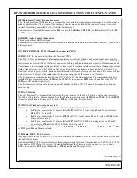
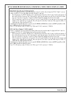
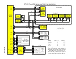
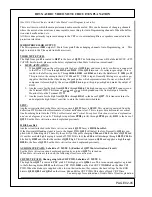
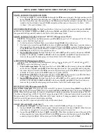
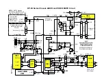
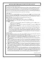
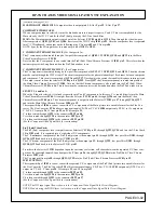
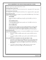
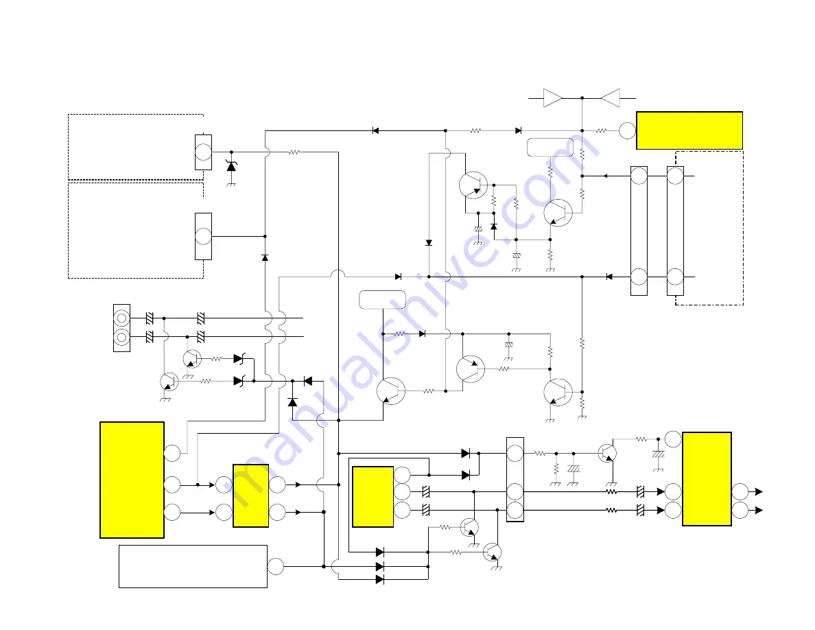
Страница 30: ...5A1 to the base of Q527 This transistor turns On and outputs the high from it s emitter to mute the Audio described later SPOT Another circuit attached to the Mute Activation circuit Q529 base is SPOT This signal is generated from the deflection PWB when either Horizontal or Vertical deflection is lost This is to prevent a horizontal or vertical line from being burnt into the CRTs See Horizontal a...

Страница 31: ...ront Audio signal mute The high from the Level shifter I007 pin 13 is routed to the anode of DA04 and to the base of QA01 and QA02 When these transistor turns on they ground the audio going into the Audio Output IC IAA1 at the PPS4 connector Right audio in pin 2 of the PPS4 connector to pin 4 of IAA1 Left audio in pin 3 of the PPS4 connector to pin 2 of IAA1 2 Main Tuner U301 Mute The high from th...

Страница 32: ...99 V MUTE R5A3 R5A7 Q528 4 Spot Q529 R5A4 HVcc 9 3V R546 D511 C547 D510 R5A5 R5A1 Q527 V MUTE 2 CRT PWB PSC 565 R561 D516 R5K6 Q523 FC H Blk Q522 FC V Blk PST1 V MUTE 1 11 8 PPD3 4 Deflection PWB HVcc 9 3V NOTE V MUTE 1 becomes V MUTE 2 on Signal PWB 2 3 Then V MUTE 1 again on CRT PWB D503 R564 Right CA52 CA55 Left QA54 CA51 CA54 JA01 R L DA53 Out To Hi Fi See Sweep Loss Detection Circuit Diagram ...

Страница 33: ...t to the Microprocessor at Pin 92 Sub AFC is generated from the Sub Tuner U302 pin 16 Then routed to Q035 and Q036 Then into pin 92 of the Microprocessor The Microprocessor uses this input signal to align or adjust the precise Oscillator and Programmable divider settings within the PinP Tuner for proper Reception 100 MAIN CCD IN The Microprocessor receives Main Sync information and strips the Clos...

Страница 34: ... 25 Sub CCD Sel SD Sel Q003 Q004 Q010 Q009 Q008 39 2 12 5 Sub 1 13 480i Sub CCD In Main CCD In 480i Composite 2 Q005 Q006 16 SW 9V Y In 480i IX02 Q025 Q014 Sub Y Video PiP Video and Sub Video are the same Q007 17 19 V3 S4 15 10 12 V5 S5 22 24 26 Front Control PWB V4 8 U301 Main Tuner 63 60 50 45 Aux 5 S Y V3Y Aux 5 S C V3C Aux 5 Video V3V 2 7 9 PFT 18 18 V3 Y3 C3 V2 Y2 C2 V4 Y4 C4 V6 TV S 3 S 4 De...

Страница 35: ...DP 3X CHASSIS INFORMATION VIDEO INFORMATION SECTION 3 ...

Страница 36: ...DP 3X BLANK PAGE NOTES BLANK PAGE ...

Страница 37: ...ideo output for recording purposes This is accomplished by the ATSC Digital Tuner having a Y C output sent to the NTSC circuit for this purpose AUXILIARY INPUT This chassis utilizes 5 separate inputs plus a newly added input called DVI The following will break down those input routes to the Selector IC IV01 Some models will also have a built in DVD player for 6th input 1 INPUT 1 This input is only...

Страница 38: ...and into the Main Video Chroma Processor IY04 pin 4 The Chroma component is output from the Selector IC IV01 pin 47 through QV16 QV17 and into the Main Video Chroma Processor IY04 pin 19 The responsibility of IY04 is to now convert the Y C components of the Main picture into a usable format for the Flex Con verter The Flex Converter FC4 utilizes component inputs Y Pr Pb or Y Cr Cb IY04 outputs onl...

Страница 39: ...58 56 51 49 53 47 44 2 7 9 PFT 13 15 4 18 18 QV24 XV01 2 3 QV25 QV26 QV28 QV29 QV30 QV32 XV02 3 2 2 Y1 QV17 C Out ACO Y Out AYO 16 C1 QY16 Sub Video Chroma Processor Y1 In C1 In 16 2 QY17 23 24 22 SEE DVI and DVD SIGNAL PATH DIAGRAM for DVI and DVD FLOW V3 Y3 C3 V2 Y2 C2 V4 Y4 C4 V6 TV DP 3X CHASSIS VIDEO SIGNAL PATH NTSC TERMINAL PWB 23 22 24 QY24 QY23 PST2 26 27 29 QY22 See the Video Signal Path...

Страница 40: ...uts Y Pr Pv 31 5Khz to 33 75Khz ATSC only See DVI Signal Path for further details The G line is input from the PET connector pin 14 into the Y Pr Pb Selector IV04 pin 8 The R line is input from the PET connector pin 12 into the Y Pr Pb Selector IV04 pin 16 The B line is input from the PET connector pin 16 into the Y Pr Pb Selector IV04 pin 11 4 DVI 2 INPUT Digital Video Interface This input will a...

Страница 41: ...T2 connector pin 26 to U401 Flex Converter pin 19 Pb pin 23 to QY23 to PST2 connector pin 27 to U401 Flex Converter pin 18 MAIN SIGNAL FROM FLEX CONVERTER U401 The Flex Converter outputs only one horizontal frequency and that is 33 75Khz 540P which relates specifi cally to 1080i deflection rate So in other words all inputs NTSC 480i 480P 720P 1080P are upconverted to the higher deflection rate 108...

Страница 42: ...ontrol DVI2 R DVI2 G DVI2 B In1A In3A In2A V1 9 14 1 PET See DVI Input Signal Diagram 11 8 16 14 16 12 6 5 3 OUT 1 OUT 2 OUT 3 6 Control In1B In2B In3B DVI1 R DVI1 G DVI1 B In1A In3A In2A Lo Y Pr Pb Hi DVI 1 Lo Y Pr Pb Hi DVI 2 63 61 59 Y PB PR 9 7 5 Y PB PR I N P U T 2 31 32 LOut 1 LOut2 20 11 IV04 Selector Y Pb Pr DVI 1 DM HY DM PB DM PR 19 17 15 PST1 23 25 26 From ATSC Digital Tuner UD2002 Main...

Страница 43: ... Converter via connector PFC2 Pin 8 The clamp pulse is utilized for DC restoration and blanking timing Pin 79 YM P MUTE BLK Combination of the following INTERNAL 0 0V 0 5V Used internal within the Rainforest IC HALFTONE 1 2V 1 8V This input is received from the Microprocessor and is used to establish the Transparency effect of OSD This also mutes the video in exact timing with On Screen Display pu...

Страница 44: ...ll voltage away from pin 78 of the Rain forest IC I501 Internally this reduces the contrast and brightness voltage which is being controlled by the I2 C bus data communication from the Microprocessor arriving at pins 29 and 30 of the Rainforest IC and reduces the overall brightness preventing blooming as well as reducing the Color saturation level to prevent color smear BLACK PANEL SWITCH QH05 Thi...

Страница 45: ...1 Gnd DH13 CH17 IH01 7 DH14 RH09 CH10 RH23 LH06 Stops H Drive OVP HZ22 2L RH26 PPD3 PPS3 Power Supply PWB 6 8K FBT RH36 180K RH37 Micro I001 SDA2 SDA2 29 SCL2 SCL2 30 31 28 R572 R571 ABL Switch 75 HVcc 9 3V 63 1080i Y In QH04 PPD5 9 10 ABL Switch PAGE 03 09 ABL Black Panel RH21 LH01 CH14 RH28 39K RH24 43K 48 ABL Switch Black Panel 23 DAC2 ABL Switch RH38 47K RH39 Black Panel QH05 50P B C RH42 RH41...

Страница 46: ...der Media Bridge is input from the PBT con nector pin 10 and arrives at IV07 pin 13 Which ever signal source is selected the V Sync MVD Out is sent out pin 14 to the base of QY32 to the PST2 connector as described above Sub Y Output from IY03 The Sub signal either component or composite is sync separated inside IY03 and output The following de scribes it s associated output path H sync pin 17 to Q...

Страница 47: ...Main V Out D Sync 1 Y3 G In NTSC Y In S In Y In 28 6 29 30 D Sync 2 In Y In Cb Pb B In Cr Pr R In 4 19 D Sync 1 Y3 G In NTSC Y In S In Y In Sub H Out Sub V Out I502 X Lo Hi 11 12 16 7 8 Sub H In Sub V In Main H In Main V In HD Out VD Out 52 I501 DAC 1 50 HD In 14 13 HVcc 9 3V VD In DP 3X MAIN COMPONENT SYNC CIRCUIT DIAGRAM 34 PAGE 03 11 14 13 13 Bridge Media V Sync Pin 10 PBT MVD IV07 IY03 IY04 MV...

Страница 48: ...CI L R Y C Analog Audio NTSC Video Analog Power Supply PTV Signal Board HD Video Y Pr Pb SCI Digital Power Supply CPU bus Y Pb Pr 16MB FLASH SCI 64MB SDRAM SH4 Main CPU Sub CPU Optical 64MB SDRAM DAC DAC NTSC Encoder Graphics Peripherals YSD 038 Graphics DAC Glue Logic 1 2 L R Y C V I2 C Memory Card I F Memory Card Board Memory Card I F SPD I F Memory Card I F ATSC CATV RF IN Main Board TS in TS o...

Страница 49: ...41 38 37 17 13 Reset DVcc Vcc DACVcc 22 32 DACVccB Vcc DVcc Vcc 7 1 AVcc AVcc DJ10 DJ12 DJ09 QJ05 18 19 4 1 19 18 DVIV DVIH VSync HSync 12 14 26 23 DVIG DVIR IOG IOR QJ03 QJ02 16 31 DVIB IOB QJ01 20 40 DVIDET SCDT QJ04 6 8 15 3 5 NC NC 13 Reset SW 5 5 DVIV DVIH DVIG DVIR DVIB DVIDET GND GND GND GND GND 10 12 16 21 25 28 33 35 43 45 50 4 All of these pins are ground LJ17 1 7 LJ15 3 1 2 DJ08 3 1 2 D...

Страница 50: ...DP 3X BLANK PAGE NOTES BLANK PAGE ...

Страница 51: ...DP 3X CHASSIS INFORMATION AUDIO INFORMATION SECTION 4 ...

Страница 52: ...DP 3X BLANK PAGE NOTES BLANK PAGE ...

Страница 53: ...D Player Front Audio input L pin 12 and R Pin 2 DVD Audio L pin 13 and R pin 1 It outputs selected audio L from pin 14 and R from pin 15 to IV01 L pin 23 and R pin 25 MONITOR OUTPUTS 38 Left and 40 Right This is the Monitor Audio Outputs LEFT and RIGHT OUTPUTS 43 Left and 45 Right This is the Left Total and Right Total output which represent the Audio associated with the Main picture The Lt and Rt...

Страница 54: ...1 R In IA01 NJW1160 Audio Control L In 15 14 L Out 8 Left R Out 23 Right CAE3 CAE4 QA53 QA52 QA56 QA55 L 28 31 I001 R QA01 See AV Mute Circuit Diagram See AV Mute Circuit Diagram QA02 FL WO Out QA54 QA51 Left Out Right Out Micro PST1 UD2003 ATSC Tuner 4 2 DM R DM L 29 28 13 14 Tuner Audio Digital Tuner Audio Left Input 4 Right Left Input 2 Right Left Input 1 Right Left Input 3 Right Left Input 5 o...

Страница 55: ...d pin 26 Left Through C099 Right C098 Left To I301 pin 1 Right pin 13 Left Sub Tuner 302 PinP Tuner From pin 27 mono audio To Q050 Through C086 To I301 pin 2 Right pin 12 Left I301 Main Sub Selector IC The Audio inputs are selected by the control lines at pins 10 and 11 These pins are controlled by the output from the Microprocessor I001 pin 72 through inverter Q033 Pins 10 and 11 High Main Tuner ...

Страница 56: ...6 Q050 C086 X Lo Hi HVcc 9 3V 16 12 13 Y Lo Hi 1 2 15 14 I301 10 11 47 48 Q033 C099 C098 27 I001 MICRO 72 TVAUDSEL TV R TV L IV01 A V Select 64 62 DP 3X MAIN SUB AUDIO SELECT CIRCUIT DIAGRAM PAGE 04 04 Pins 10 and 11 High Main Tuner Pins 10 and 11 Low Sub PinP Tuner ...

Страница 57: ...DP 3X CHASSIS INFORMATION DEFLECTION INFORMATION SECTION 5 ...

Страница 58: ...DP 3X BLANK PAGE NOTES BLANK PAGE ...

Страница 59: ... connector pin 8 to pin 39 of I501 as FBP In Here this signal is used as a comparison signal It is compared to the reference signal coming in at pin 50 Horizontal Sync If there are any differ ences between these two signals the output Drive signal from pin 37 is corrected NOTE When a 1080i signal is input through component inputs the Reference signal for Horizontal Sync now becomes the H Sync befo...

Страница 60: ... pin 3 and DN09 to pin 14 If these voltages go high pin 3 will defeat the H Drive by saturating the internal op amp that creates the sawtooth comparator signal Thus stopping H Drive Pin 14 high will satu rate the internal generator that produces the sine wave for the sawtooth op amp See Figure 1 below DC Ref Gen DC Ref DC Feed Back 3 9 12 10 11 1 Fig 1 GENERAL INFORMATION The DP 3X deflection circ...

Страница 61: ...Com1 E r r o r 1 To Micro for OSD Auto Prog SD AFC 63 1080i for Through Mode See Voltage and Waveform Chart on next page Y2 In Rainforest IC 8 6 PPD3 Power Supply PWB I503 3 5 SW 10V R748 R730 D715 C725 R735 D709 Side Pin Modulator 2 Q709 Q706 To Dynamic Focus QF01 RH07 CN01 14 PDG DH04 11 RH22 DH05 9 QH02 QH01 Horizontal Output 9 PPD5 10 SW 115V Ref V 12 DH01 SW 10V 2 PPD4 RH02 RH01 CN01 7 OVP RH...

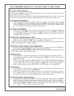
Страница 62: ...tputs a high from QN02 This high is used to shut off the CRT to prevent CRT burn How ever the Collector of QN02 is also routed to these two pins through diodes DN09 to pin 14 and DN10 to pin 3 When QN02 goes high it drives pin 3 and 14 high which turns off the internal oscillator of IH01 via pin 3 This action stops Horizontal Drive to the High Voltage circuit This action causes pin 1 to satu rate ...

Страница 63: ...ain this is done to prevent CRT burn es pecially during sweep loss This high is also routed through RN16 DN10 to pin 3 of IH01 which also kills the internal drive CONCERNING QN02 There are several factors that can cause QN02 to activate loss of vertical or horizontal blanking Loss of Vertical Blanking V Blk The Vertical pulse at the base of QN05 switches ON05 on and off at the vertical rate This d...

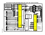
Страница 64: ...1 IH01 High Voltage Driver IC 4 From I001 Micro Pin 47 Spot Inhibit When Vertical Drive is turned Off during adjustment I 2C SW 10V RN15 Stops Drive RN16 RH07 Stops High Voltage Drive Signals From being produced when Sweep Loss is detected RN18 PPD3 RN17 5 CUT OFF RN12 RN14 To Q529 Signal 3of 3 See A V MUTE Circuit DN12 DN08 DN06 DN07 DN11 QN06 4 PPS3 5 DN02 DN03 QN03 QN02 DN10 DN09 QN04 QN05 Stop...

Страница 65: ...the Vertical Blanking pulse It s amplitude is around 21V p p and is sent to the following circuits Vertical Sweep Loss detection circuit Convergence circuit for vertical correction waveform generation To the PPD3 PPS3 connector pin 12 to be sent to various circuits on the signal PWB The Micro processor uses this signal to time it s OSD VERTICAL OUTPUT PULSE The Vertical Output pulse is then routed...

Страница 66: ...00 25 R620 1 2 ohm R621 C608 To Side Pin Cushion Circuit To Dynamic Focus Circuit 6 Gnd Vs 28V D603 C604 7 Ramp Gen 5 C602 NC R602 D601 4 Hight Adj V Def Yoke G V Def YokeR 11 Flyback Gen C605 Charge Pump R614 V OUT L601 R619 1 2 ohm V Blk To Vertical Sweep Loss Detection Circuit To Conv Circuit Protect_Def D608 Q604 R629 0 68 R631 R630 C610 10 D Size Q603 R607 V Size R608 R618 L602 V V V V V V V ...

Страница 67: ... is connected through pin 5 to the feedback circuit from the Side Pin Cushion output circuit for stability The output of the DC offset voltage with Vertical parabolic wave form attached is then routed out pin 7 to the base of Q703 This transistor has its emitter off set above ground by D713 R747 back to the SW 9V and R704 This transistor drives the base of the Side Pin Cushion modulator transistor...

Страница 68: ...3 R714 Q701 Q710 R704 D713 R708 R747 R707 R706 D701 R715 C701 C722 R721 SW 11V R710 R711 R713 R712 D714 H Size Adj R709 C702 R742 V Parabolic C715 L703 R729 8 96V 4 39V 5 17V 5 14V 6 1 Q777 7 8 T701 Deflection Horizontal Driver Sensor Initialize Hi Magic Focus Hi To H Linearity off H Yoke Returns L704 L705 To H Deflection Yokes R756 ...

Страница 69: ...DP 3X CHASSIS INFORMATION DIGITAL CONVERGENCE INFORMATION SECTION 6 ...

Страница 70: ...DP 3X BLANK PAGE NOTES BLANK PAGE ...

Страница 71: ... CRTs is what is used by the sensors for Magic Focus This allows the DCU to make adjustments regardless of circuit or mechanical changes or magnet influence by actually using the light on the screen to make judgments EEPROM AND SRAM SHOWN IN FIGURE 1 8 Sensor Array Each color can be adjusted in any one of 117 different locations The internal workings of the DCU can actually make 256 adjustment poi...

Страница 72: ...l not allow Magic Focus to operate If the Magic Focus button is pressed the screen will display an adjustment grid instead This is done by pressing the PIP MODE button on the remote one 1 time then pressing the SURF button This begins a preprogrammed generation of different light patterns Magic Focus memory memorizes the characteris tics of the light pattern produced by the digital convergence mod...

Страница 73: ...I501 at pins 26 Dig Red 25 Dig Green and 24 Dig Blue When a character pulse arrives at any of these pins the internal color amp is saturated and the output is generated to the CRTs Any combination for these inputs generates either the pri mary color Red Green or Blue or the complementary color Red and Green which creates Yellow Red and Blue which creates Magenta or Green and Blue which creates Cya...

Страница 74: ...must be able to run Press Magic Focus button on front panel while its running press the Magic Fo cus button in and hold Stop will be displayed Press the INFO button on the remote while STOP is dis played MAGIC FOCUS SWITCH Located on the Front Control panel is the Magic Focus switch When Magic Focus is activated by the cus tomer pressing this switch the DCU enters the MAGIC FOCUS adjustment mode d...

Страница 75: ...R In 7 1 MAG SW SM09 GV 5V 5V MAG SW 1 5 Magic Focus 8 I010 3 3V 5V 8 Q516 Q515 Q521 Q520 Q519 21 19 18 24 25 26 QK06 QK07 QK08 Rainforest Dig OSD B Dig OSD G Dig OSD R OSD B OSD G OSD R B G R 4 8 5 7 3 1 Service Only BUSY QM01 32 34 33 OSD B OSD G OSD R Magic Sw Out 44 42 IR I001 Main Up From IK01 12 Dig Adj D Size 21 22 RK23 DK53 11 10 12 22 N C PDS PDS 6 PPD1 PPS1 45 Digicon Busy In QM05 Magic ...

Страница 76: ...T BLUE 13X9 REMOVE COLOR CALCULATE INITIALIZE PIP MODE SURF WRITE TO ROM PRESS 2X READ OLD ROM DATA PRESS 2X CENTERING RASTER POSITION GREEN 3 X 3 CORRECTION BUTTONS CROSSHATCH VIDEO RASTER PHASE RED 7 X 5 PAGE 06 06 CURSOR UP CURSOR RIGHT CURSOR DOWN PIP ACCESS C C ASPECT VID 1 VID 2 VID 3 VID 4 VID 5 DAY NIGHT DP 37 REMOTE CONTROL CLU 5728TSI P N HL01828 DP 37 51S500 57S500 65S500 Must be in VCR...

Страница 77: ...X9 REMOVE COLOR CALCULATE INITIALIZE PIP MODE SURF WRITE TO ROM PRESS 2X READ OLD ROM DATA PRESS 2X CENTERING RASTER POSITION GREEN 3 X 3 CORRECTION BUTTONS CROSSHATCH VIDEO RASTER PHASE RED 7 X 5 PAGE 06 07 CURSOR UP CURSOR RIGHT CURSOR DOWN VIRTUAL HD ASPECT VID 1 VID 2 VID 3 VID 4 VID 5 ZOOM DP 33W REMOTE CONTROL CLU 5727TSI P N HL01825 46W500 SUB TITLE PiP SURF FRZ MODE DAY NIGHT Must be in VC...

Страница 78: ...X9 REMOVE COLOR CALCULATE INITIALIZE PIP MODE SURF WRITE TO ROM PRESS 2X READ OLD ROM DATA PRESS 2X CENTERING RASTER POSITION GREEN 3 X 3 CORRECTION BUTTONS CROSSHATCH VIDEO RASTER PHASE RED 7 X 5 PAGE 06 08 CURSOR UP CURSOR RIGHT CURSOR DOWN PIP ACCESS C C ASPECT VID 1 VID 2 VID 3 VID 4 VID 5 DAY NIGHT DP 37 REMOTE CONTROL CLU 5725TSI P N HL01825 DP 37C 57T500 65T500 and DP 37D 57X500 65X500 Must...

Страница 79: ...18 2 81 8 81 8 81 8 81 8 81 8 81 8 81 8 81 8 VERTICAL SIZE 505mm HORIZONTAL SIZE 930mm PART NUMBER H312275 81 8 NOTE Aspect may not be correct but dimensions are correct DIGITAL CONVERGENCE OVERLAY DIMENSIONS 46W500 DP 33W Chassis OVERLAY DIMENSIONS NORMAL MODE RED OFFSET 20mm BLUE OFFSET 35mm PAGE 06 09 ...

Страница 80: ...19 7 90 8 90 8 90 8 90 8 90 8 90 8 90 8 90 8 VERTICAL SIZE 560mm HORIZONTAL SIZE 1020mm PART NUMBER H312272 90 8 NOTE Aspect may not be correct but dimensions are correct DIGITAL CONVERGENCE OVERLAY DIMENSIONS 51S500 DP 37 Chassis OVERLAY DIMENSIONS NORMAL MODE RED OFFSET 20mm BLUE OFFSET 25mm PAGE 06 10 ...

Страница 81: ... 57X500 DP 37D CHASSIS OVERLAY DIMENSIONS NORMAL MODE B R H SIZE V SIZE Centering Offset 1262 34 1 45 8 91 7 91 7 91 7 91 7 91 7 91 7 45 8 34 1 22 0 101 5 710 22 0 101 5 101 5 101 5 101 5 101 5 101 5 101 5 101 5 VERTICAL SIZE 625mm HORIZONTAL SIZE 1140mm PART NUMBER H312273 101 5 RED OFFSET 20mm BLUE OFFSET 25mm PAGE 06 11 ...

Страница 82: ... OVERLAY DIMENSIONS NORMAL MODE B R H SIZE V SIZE Centering Offset 1439 38 6 52 1 104 6 104 6 104 6 104 6 104 6 104 6 52 1 38 6 25 3 115 7 809 19 7 115 7 115 7 115 7 115 7 115 7 115 7 115 7 115 7 VERTICAL SIZE 710mm HORIZONTAL SIZE 1300mm PART NUMBER H312274 115 7 RED OFFSET 20mm BLUE OFFSET 25mm PAGE 06 12 ...

Страница 83: ...DP 3X CHASSIS INFORMATION ADJUSTMENT INFORMATION SECTION 7 ...

Страница 84: ...DP 3X BLANK PAGE NOTES BLANK PAGE ...

Страница 85: ...e EXIT key This is the Phase adjustment mode 6 Adjust data value using the keys indicated in the chart until the data matches the values indi cated in the chart Exiting Adjustment Mode 7 Press PHOTO key on remote control 8 Press PIP MODE key TWICE to store the information 9 When Green dots are displayed press the MUTE key twice to re turn to DCAM grid DCA stands for Digital Convergence Adjustment ...

Страница 86: ...gle between Video mode and DCU Grid 3 Select GREEN A CH and press the MENU but ton to remove Red and Blue 4 Adjust using R607 Vertical Size Adj VR to match sizes in the Table Below NOTE Centering magnet may be moved to facilitate Distance is important not centering NOTE Do not use the Hash marks on the Overlay as they may be incorrect and or the Vertical Size may change to improve performance Scre...

Страница 87: ...l toggle between Video mode and DCU Grid Project only the Green raster by selecting Green Adjustment mode and press ing the MENU button on remote ADJUSTMENT 1 Adjust using R711 Horz Size Adj VR Ad just Horizontal Size until the size matches the chart below 2 Press Power Off to exit DCAM Digital Conver gence Adjustment Mode NOTE Do not use the Hash marks on the Overlay as they may be incorrect and ...

Страница 88: ...entering DCAM with each press of the Service Only Switch the picture will toggle be tween Video mode and DCU Grid Video Control should be set at Factory Preset condition Static Focus adjustment should be finished Adjustment Procedure 1 Turn the centering magnets of Red Green and Blue and adjust so that the center point of the cross hatch pattern satisfies the diagram and Offset Value Table below D...

Страница 89: ...o make data value changes Press the Cursor Left and Right keys ADJ PARAMETER ADJ DISP 0F DEMO WAIT 1F INT START 13 V SQUEEZE 10 4 Press the PIP MODE MODE in DP 33W key 2 times to write the changed data into EEPROM First press ADJ PA RAMETER ROM WRITE Is displayed for alarm 2nd press writes data into EEPROM Green dots ap pear after completion of operation 5 Press the MUTE button 3 times exit back t...

Страница 90: ... and Right buttons to change the Pat tern Position Data in horizontal Direction Press the Thumb Stick Up and Down buttons to change the Pattern Position Data in Ver tical Direction 6 Set the Data Values as shown in the Table below 7 Press the PIP MODE MODE on DP 33W key 2 times to write the changed data into EEPROM First press ADJ PARAME TER ROM WRITE Is dis played for alarm 2nd press writes data ...

Страница 91: ...ress Screen goes black then re appears with green dots Press the MUTE button to return to Digi tal convergence grid EXAMPLE Sometimes the Magic Focus will not run cor rectly and will return an error code Sometimes after Magic Focus is run but the convergence appears off after completion OTHER IMPORTANT INFO Many times after a complete adjustment when initializing the Magic Focus sensors an error c...

Страница 92: ...LEFT BLUE 13X9 REMOVE COLOR CALCULATE INITIALIZE PIP MODE SURF WRITE TO ROM PRESS 2X READ OLD ROM DATA PRESS 2X CENTERING RASTER POSITION GREEN 3 X 3 CORRECTION BUTTONS CROSSHATCH VIDEO RASTER PHASE RED 7 X 5 PAGE 07 08 CURSOR UP CURSOR RIGHT CURSOR DOWN PIP ACCESS C C ASPECT VID 1 VID 2 VID 3 VID 4 VID 5 DAY NIGHT DP 37 REMOTE CONTROL CLU 5728TSI P N HL01828 51S500 57S500 65S500 Must be in VCR Mo...

Страница 93: ...X9 REMOVE COLOR CALCULATE INITIALIZE PIP MODE SURF WRITE TO ROM PRESS 2X READ OLD ROM DATA PRESS 2X CENTERING RASTER POSITION GREEN 3 X 3 CORRECTION BUTTONS CROSSHATCH VIDEO RASTER PHASE RED 7 X 5 PAGE 07 09 CURSOR UP CURSOR RIGHT CURSOR DOWN VIRTUAL HD ASPECT VID 1 VID 2 VID 3 VID 4 VID 5 ZOOM DP 33W REMOTE CONTROL CLU 5727TSI P N HL01825 46W500 SUB TITLE PiP SURF FRZ MODE DAY NIGHT Must be in VC...

Страница 94: ...X9 REMOVE COLOR CALCULATE INITIALIZE PIP MODE SURF WRITE TO ROM PRESS 2X READ OLD ROM DATA PRESS 2X CENTERING RASTER POSITION GREEN 3 X 3 CORRECTION BUTTONS CROSSHATCH VIDEO RASTER PHASE RED 7 X 5 PAGE 07 10 CURSOR UP CURSOR RIGHT CURSOR DOWN PIP ACCESS C C ASPECT VID 1 VID 2 VID 3 VID 4 VID 5 DAY NIGHT DP 37 REMOTE CONTROL CLU 5725TSI P N HL01825 DP 37C 57T500 65T500 and DP 37D 57X500 65X500 Must...

Страница 95: ...the normal Convergence Cross Hatch pattern Figure 1 Marker Marker Marker Only Box Marker Press the Menu button on the remote control Only display color selected for adjustment Note Green always appears in this case Red is selected so Red and Green yellow lines appears Figure 2 Press the Menu button again and the Crosshatch appears on the main picture Figure 3 Press the Menu button again Marker plu...

Страница 96: ... Application Initialize Magic Focus 1 VF Error Replace DCU X X 2 2 Connect 1 1 Darken Outside Light 2 Placing of Sensor 3 Is pattern hitting sensor 4 Check connection and solder bridge of sensor 5 Replace Sensor 6 Replace Sensor PWB 7 Sensor Connector check 8 Replace DCU 9 Adjustment check H V size centering X 3 2 A D Level Same as Error Code 2 X X 4 Over Flow 1 Check the placement 2 Adjustment ch...

Страница 97: ... 5 FRONT 4 7 8 9 Red Green Blue Focus Controls Also Screen Controls for Red Green Blue 1 Centering magnet RED 2 Centering magnet GREEN 3 Centering magnet BLUE 4 Beam Form Magnets 5 Beam Alignment magnets 6 Focus Block Assembly 7 RED Yoke 8 GREEN Yoke 9 BLUE Yoke PAGE 07 13 ...

Страница 98: ...DP 3X BLANK PAGE NOTES BLANK PAGE ...

Страница 99: ...DP 3X CHASSIS INFORMATION MISCELLANEOUS INFORMATION SECTION 8 ...

Страница 100: ...DP 3X BLANK PAGE NOTES BLANK PAGE ...

Страница 101: ...PFSH2 PAS1 PBS PSC EH7P PH2P EH13P PH10P EH2P EH10P VH12P PH12P I501 I001 U302 Sub Tuner U301 Main Tuner TERMINAL PWB DVI PWB FLEX CONTROL PIP U401 DIGITAL MODULE DP 36 38 38D REAR VIEW DP 3X CHASSIS SIGNAL PWB PAGE 08 01 ...

Страница 102: ...H Size Adj V Size Adj CONVERGENCE SERVICE SWITCH IK01 PADJ QK01 D708 1 6 1 1 6 PPD1 PPD2 PPD3 PPD6 1 10 1 7 12 7 1 PDS1 PCR RED PCG GREEN PCB BLUE M62501P IH01 T702 T701 1 11 CH16 RH17 HV ADJ DO NOT ADJ 1 UKDG DIGITAL CONVERGENCE UNIT DP 3X CHASSIS DEFLECTION PWB PAGE 08 02 ...

Страница 103: ...Power Relay D912 Main POWER Red LED PPD3 PPD4 PPD5 E905 B Reg D956 Audio Green D955 SW 5 5V Green D932 B Green D913 Sby 5V Green PPS3 PPS4 PPS5 IAA1 1 12 EAG1 Audio Gnd 1 5 I903 FB T901 Switching Transformer U901 Stand by Module I902 ACK E902 10V E901 Audio E904 28V E905 28V E903 220V PPC2 PPS6 DP 3X CHASSIS POWER SUPPLY PWB PSP PAGE 08 03 D954 28V Green PPD2 ...

Страница 104: ... 3X CHASSIS CRT PWB E801 RED P802 Cathode P801 1 3 GND E851 GREEN P852 Cathode P851 1 3 GND E8A1 BLUE P8A2 Cathode P8A1 1 3 GND R R G G B B FOCUS PACK FOCUS PACK UFPK SCREEN ADJ VR FOCUS ADJ VR PAGE 08 04 ...

Страница 105: ...DP 3X CHASSIS FRONT CONTROL PWB PFT PF1 PFS POWER LED Blue Except DP 33W IR RECEIVER MAGIC FOCUS VOL VOL CH CH INPUT EXIT MENU SELECT R L V S EF1 IR RECEIVER FOR AV NET IR RECEIVER FOR REMOTE PAGE 08 05 ...

Страница 106: ...s S Out only available with S Inputs 4 OUT TO HI FI Variable Audio outputs 5 CENTER IN When the TV is set to TV as Center it receives it s input from this source 6 S VIDEO INPUTS 3 and 4 7 Y Pr Pb For inputs 1 and 2 Input 2 will also accept composite video on the Y input without a Pr plug Also accepts Y Cr Cv NTSC 480i 8 DVI HDTV IN Accepts Digital Video interface connections for 1080i 720P 480P a...

Страница 107: ...r loops Antenna A out while set is in Antenna B mode 2 AUDIO VIDEO INPUTS 1 2 3 4 and 5 S Video for inputs 3 4 and 5 only 3 MONITOR OUT Video and Fixed Audio outputs S Out only available with S Inputs 4 OUT TO HI FI Variable Audio outputs 5 CENTER IN When the TV is set to TV as Center it receives it s input from this source 6 S VIDEO INPUTS 3 and 4 7 Y Pr Pb For inputs 1 and 2 Input 2 will also ac...

Страница 108: ...tenna B mode 2 AUDIO VIDEO INPUTS 1 2 3 4 and 5 S Video for inputs 3 4 and 5 only 3 MONITOR OUT Video and Fixed Audio outputs S Out only available with S Inputs 4 OUT TO HI FI Variable Audio outputs 5 CENTER IN When the TV is set to TV as Center it receives it s input from this source 6 S VIDEO INPUTS 3 and 4 7 Y Pr Pb For inputs 1 and 2 Input 2 will also accept composite video on the Y input with...

Страница 109: ...O VIDEO INPUTS 1 2 3 4 and 5 S Video for inputs 3 4 and 5 only 3 MONITOR OUT Video and Fixed Audio outputs S Out only available with S Inputs 4 OUT TO HI FI Variable Audio outputs 5 CENTER IN When the TV is set to TV as Center it receives it s input from this source 6 S VIDEO INPUTS 3 and 4 7 Y Pr Pb For inputs 1 and 2 Input 2 will also accept composite video on the Y input without a Pr plug Also ...

Страница 110: ...and 2 Input 2 will also accept composite video on the Y input without a Pr plug Also accepts Y Cr Cb NTSC 480i 8 DVI HDTV IN Accepts Digital Video interface connections for 1080i 720P 480P and 480i 11 OPTICAL OUT Used to connect to equipment with optical audio inputs This is DVD Digital Audio Pr Pb Y R MONO L AUDIO DVI HDTV INPUT 1 R VIDEO R MONO L AUDIO INPUT 2 INPUT 3 MONO L S VIDEO R VIDEO INPU...

Страница 111: ...DP 3X CHASSIS INFORMATION DP 33W 46W500 DVD PLAYER TROUBLESHOOTING SECTION 9 ...

Страница 112: ...DP 3X BLANK PAGE NOTES BLANK PAGE ...

Страница 113: ...erly Terminal PWB Defect Check pin 1 and 28 for 5V 5V OK IU01 Defect CU01 CU02 CU03 Defect DVD Loader Defect Ensure that pins 12 14 and 16 of PAA2 are OK Ensure that EAA1 and EAA2 are connected Ensure EAA1 goes to PAA1 Ensure EAA2 goes to PAA2 5 No DVD Picture DP 33W NG OK NG OK OK NG NG NG OK OK OK NG All checks on the DVD Power Supply PWB No 5V check DU13 LU01 LU95 IU95 6 No DVD Analog Audio DP ...

Страница 114: ...D Loader Defect DVD Loader Defect Ensure that there is more than 2 7V at the base of QU01 and QU02 Ensure EAA1 goes to PAA1 Ensure EAA2 goes to PAA2 Components of L or R rails are missing Ensure that L and R at pin 2 and 6 of IU03 are OK IU03 Defect Ensure that EAA1 and EAA2 are connected Ensure that L and R at pin 4 and 6 of PAA2 are OK 6 No DVD Analog Audio DP 33W NG OK NG OK OK NG NG OK OK OK N...

Страница 115: ...B Defect LU06 Defect DVD Loader Defect Ensure that SPDIF at pin 1 of LU06 is OK Ensure that EAA2 is connected Ensure EAA2 goes to PAA2 Ensure that SPDIF at pin 1 of PAA2 is OK Ensure that SPDIF at base of of QU07 is OK QU07 Defect RU13 is missing NG OK OK NG NG OK OK OK NG All checks on the DVD Power Supply PWB OK OK NG NG NG 7 No DVD Digital Audio DP 33W Page 09 03 ...

Страница 116: ...een pin 2 and 3 Connect 1K ohm between QU93 base and GND Remove 1K ohm between QU93 base and GND Is the 1 5V 3 3V 5V and 9V shut down 8 DVD PWB Ass y Operation Check a DVD Power Supply Check 1 5V PAA1 Pins 1 2 3 3 3V PAA1 Pins 4 5 17 5V PAA2 Pin 2 5V PVS2 Pin 1 No No Yes Yes This simulates Power On This simulates a Shut Down Event Relay SU91 should turn off 5V PAA1 Pins 13 9V PAA1 Pins 14 15 8 DVD...

Страница 117: ...f PVS1 connector Does the voltage vary 3 3V 0V and 1 7V with 20 tolerance sequentially at pin 1 of PVS1 connector Is there 3 3V p p 20 500Hz square wave at pin 3 of PVS2 connector 2 IU02 defective Level Shifter IU02 defective Level Shifter Aspect circuit path defect DU07 RU14 RU15 RU16 DU19 SPDIF circuit path defect DU11 DU12 RU13 CU43 QU07 RU76 DU17 DU18 RJ19 LU06 8 DVD PWB Ass y Operation Check ...

Страница 118: ...gnal to pin 12 14 and 16 of PAA2 connector Y should be 1V p p at pin 12 Pr Pb should be 700mV p p at pins 14 and 16 Is there 1 4V p p 20 Pr Pb signal at pin 5 and 7 of PVT connector without Termination Is there 1 5Vrms 20 1Khz audio signal at pins 9 and 11 of PVT connector End 2 IU03 defective IU01 defective IU01 defective 8 DVD PWB Ass y Operation Check c DVD Audio Video Check No No Yes No Yes Ye...

Страница 119: ...FACE BLOCK DIAGRAM Video Video Video IA01 Audio Audio Audio Power Def PWB IAA1 Audio Out Audio Spk Spk CRT CRT CRT S DVD PLAYER POWER SUPPLY PWB IU01 IU03 IU02 Play FF REW Stop Eject Pause Play FF REW Stop Eject Pause IR DVD Power Control Clock Data Enable DVD IR Y Pr Pb Y Pr Pb R G B L R Y Pr Pb Y Pr Pb L R L R Rainforest PAGE 09 07 ...

Страница 120: ...Cr Pr R In QV35 6 D Sync 2 In MAIN Main Cr Pr Out Main Cb Pb Out RAINFOREST IC 4 19 TERMINAL PWB SIGNAL PWB FLEX CONVERTER IV03 Selector Y Pb Pr Main Pb Out 2 Main Y Out 2 44 42 Main Pr Out 2 40 63 61 60 Q505 Q506 Q507 Pr Out Pb Out Y Out Q508 Q509 Q510 Y Pb Pr 55 53 57 QV34 QV33 NTSC Y In S In Y In 7 9 5 PSC Q537 40 Q541 44 Q545 48 1080I Flex Bypass Y Pb Pr PAT 3 5 7 IU01 12 14 10 DVD YH DVD Pb D...

Страница 121: ...w Cont 69 DVD Enable In 67 7 PAGE 09 09 39 40 4 55 DVD IR Out SDA1 SCL1 46 47 16 17 SDA3 SCL3 33 IV01 A V Select SCL1 SDA1 IY03 Sub Video Chroma Y Pr Pb SW 13 14 IV11 DAC 14 15 DVD POWER PWB U302 Tuner PinP MODE Power _1 Power _2 Stand By Lo Lo Timer Lo Hi TV On Hi Hi When the Timer is set for an unattended Recording the Set turns on the Tuner and allows the Video Out Monitor out to become active ...

Страница 122: ... POWER PWB Cabinet Space DP 33W Chassis Only DVD Audio Signal Path PAGE 09 10 QU06 QU05 DVD R DVD L DVD L DVD R V5 Front Control PFT1 5 4 Right Left 12 2 IV08 Y1 YO X1 XO 13 1 IV01 A V Selector See Page 04 02 for continuation 23 17 25 14 15 11 10 Hi DVD Lo V5 R L X Y ...

Страница 123: ...ocated on the front right hand side just below the screen If the Open Close button is pressed with the set turned off the set will turn on and enter the DVD player screen If the set is on and the Open Close button is pressed the set will enter the DVD player screen The picture below shows a close up view of the DVD player and the escushions surrounding the player that must be removed to gain acces...

Страница 124: ...elow shows the DVD player Front Controls dropped down This allows access to to the top Left hand screw to remove the DVD player The picture below shows a close up view of the DVD player and the escushions surrounding the player that must be removed to gain access to the DVD player ...

Страница 125: ...GE 09 13 The picture below shows the screws to remove after the front escushion has been removed to remove the DVD player The picture below shows the DVD player dropped down with it s connectors identified Use the Flow Charts to identify locations for testing ...

Страница 126: ...AGE 09 14 The picture below shows the DVD player removed and separated from the PTV The picture below shows the DVD player removed and viewed from the top Note the Screws to remove the Top cover and to separated the DVD player from the Power Supply PWB be low ...

Страница 127: ... to remove the Top cover and to separated the DVD player from the Power Supply PWB be low The picture below shows the top cover removed It reveals the DVD player ribbon cables These cables must be removed to separated the DVD player from the Power supply PWB Note the Black Arrow This Ribbon cable does not need to be removed It is from the Optic assembly ...

Страница 128: ...Player from the Power Supply PWB below NOTE The three screws holding the DVD Player to the metal frame have nuts on the bottom Do not remove these screws The picture below shows the screws to remove to separated the DVD Player from the Power Supply PWB below NOTE This picture is showing the screws on the bottom side of the DVD Player ...

Страница 129: ...OTING and REMOVAL PROCEDURE PAGE 09 17 The picture below shows the DVD Player separated from the Power Supply PWB The picture below shows the DVD Player Power Supply PWB This also identifies key com ponents on the Power Supply PWB ...

Страница 130: ... Note Pins 5 and 8 of PVS1 is used as ground To turn on the Power Supply apply a 2 2 K ohm resistor between pin 2 5V and pin 3 Power On 3 This simulates a Power On command from the PTV microprocessor This will activate the relay driver QU94 to turn on the DVD power supply At this point check the following voltages DVD 9V PAA1 connector pin 14 and 15 This checks IU96 DVD 5V PAA1 connector pin 13 Th...

Страница 131: ...DP 3X CHASSIS INFORMATION THINGS YOU SHOULD KNOW SECTION 10 ...

Страница 132: ...DP 3X BLANK PAGE NOTES BLANK PAGE ...

Страница 133: ... Change All Three CRTs what to do 10 10 11 What Equipment Can I Use to Generate an HD signal 10 11 12 Does the Fan in the Digital Module Run all the time 10 11 13 The DCU appears dead no convergence correction 10 12 14 Picture Dark Abnormal Changing Color Temperature 10 12 15 The Model and Serial Number is on the Front Right Hand Side 10 13 16 DVI Input from Cable Box Causes Error Message On Scree...

Страница 134: ...DP 3X BLANK PAGE NOTES BLANK PAGE ...

Страница 135: ...b channels available sometimes there are more than one or two 8 Do they know it s respective channel on analog format NTSC Is the analog channel coming in ok Just to give you an example San Diego channel 8 NTSC is equal to channel 25 1 ATSC when you do auto programming you will see 8 1 on TV OSD but you can also enter 25 1 and you will also get to the same 8 1 digital channel We all must be very f...

Страница 136: ...ove all lead free solder from soldered joints when replacing components If leaded solder should be added to existing lead free joints mix in the leaded solder thoroughly after the lead free solder has been completely melted do not apply the soldering iron without solder Servicing soldering iron A soldering iron with a temperature setting capability temperature control function is recommended The m...

Страница 137: ... left on the screen for more than 3 minutes This screen saver will make the picture look dark and almost without color If the customer isn t aware of this feature and or haven t read their Owner s Manual Operators Guide they may mistake this for a problem A button must be pressed on the Remote Control to deactivate the Screen Saver This Screen Saver will remain in effect even if the pictures are c...

Страница 138: ... A To Converter ANT B R L AUDIO TO HI FI CENTER IN IR Blaster ANT C ATSC IN Multi Media Card IEEE 1394 OPTICAL OUT Digital Audio S VIDEO S VIDEO R VIDEO MONO L MMC goes in this direction Figure 5 MMC Fully Inserted Figure 6 Upgrade Procedure Step 1 Turn the TV ON Step 2 Using the TV Remote Select Antenna C Step 3 Press the MENU button on the Remote Step 4 Menu will appear Step 5 Press the Cursor D...

Страница 139: ...lease wait Cancel SEL Setup Upgrades Cancel Upgrade Process Upgrading 1394 Please wait Step 10 Press the Select Button Upgrade takes ap proximately 2 3 minutes Step 11 If 1394 Upgrade necessary it will start automatically Move Return SEL Setup Upgrades Upgrade Now Software Version Main V01 31 1394 V00 07 MMC Software Upgrade Please Insert MMC card before upgrade Step 12 Software Upgrade Complete I...

Страница 140: ...g auto programming in a DTV you will actually need to tune to channel 55 Because UHF channel 55 is were they are receiving the Digital Virtual channel 8 1 The Virtual Channel infor mation is embedded within the data received is the Virtual Channel ID This was decided because the Customer will know that the HDTV channel they are watching will be a known channel in their area This will help them to ...

Страница 141: ... or HORIZONTAL Line OK OK Change DCU HORIZONTAL Line VERTICAL Line No Good No Good CHECK RK45 RK46 RV CHANGE IK04 Conv Amp CHECK RK41 RK42 RH CHANGE IK04 Conv Amp HORIZONTAL Line VERTICAL Line CHECK RK53 54 BV CHANGE IK05 Conv Amp CHECK RK49 RK50 BH CHANGE IK05 Conv Amp CHECK RK61 RK62 GV CHANGE IK05 Conv Amp CHECK RK57 RK58 GH CHANGE IK04 Conv Amp VERTICAL Line HORIZONTAL Line PAGE 10 07 No Good ...

Страница 142: ... GH Pin 14 BH Fig 2 PDC Connector Pin 19 RV Pin 16 GV Pin 13 BV Fig 3 PDG Pin 16 V BLK GND Vpp 2 5 V 16 17 ms 16 17 ms 16 17 us Vpp 4 5 V PAGE 10 08 HC2191 p n CS00731 ALSO CHECK DK53 and IK02 Fig 4 PDG Pin 14 H BLK 28 30 us Vpp 4 5 V CHECK SW 7V Line D923 C940 C941 QK01 CK04 CK05 CHECK SW 6 3V Line I906 C938 IK01 5V 5V PPD4 pin 4 PPD4 pin 7 CHECK DEFLECTION CIRCUIT Horz Deflection H Blk Produced ...

Страница 143: ...C Part Number ID ID ID IK04 CZ01142 STK394 250 STK394 250 STK394 250 IK05 CZ01142 STK394 250 STK394 250 STK394 250 DCU ID Part Number UKDG HC2191 CS00731 RV 4 7 ohm GV 5 6 ohm 8 2 ohm 10 ohm 5 6 ohm 5 6 ohm BH 6 8 ohm BV 4 7 ohm 6 8 ohm 6 8 ohm 3 9 ohm 3 9 ohm RH 8 2 ohm GH 10 ohm 6 8 ohm 8 2 ohm 4 7 ohm 4 7 ohm DP 3X CHASSIS CONVERGENCE LOW OHM RESISTOR VALUES All are 1 Watt PAGE 10 09 ...

Страница 144: ...ical Output IC Drive Transformer and or Flyback Make sure the H and V Sweep Loss circuit is functioning Make sure the Yoke plugs are seated properly Clean all Spark Gaps Pry off the caps on top of each spark gap and clean the contacts with a thin fine sand paper Reinstall the caps Solder all interconnections between the Signal PWB and the Deflection PWB THINGS TO REMEMBER If at least one of the de...

Страница 145: ...least very close where only a minor touch up should be required You can do this touch up now or wait and do it after all three CRTs has been replaced 11 What equipment can I use to generate an HD signal Please see our web site at the following address http www hitachiserviceusa com service seminars DP0X Questions Questionspg2 htm 12 Does the Fan in the Digital Module Run all the time Fan Part GS00...

Страница 146: ... connector If it shorts the unit looses convergence it looks just like the unit had a defective DCU CS00731 But you can work any key unit will do all commands Additionally Magic Focus button and or Magic Focus option from R C will do absolutely nothing no effect Now if any of the other zener diodes on the Sensor PWB DL01 thru DL08 is shorted the unit will go through the motions as if doing Magic F...

Страница 147: ...se use the Y Pb Pr Outputs for your HD connection Or Monitor Does not support HDCP or Lower Resolution or Snow The warning will show up at power on and will remain there if left alone EXPLANATION This is not a problem with the Projection Television With the addition of Digital transmission many avenues of private digital data and usage privileges are being incorporated into the transmission stream...

Страница 148: ...ular Sony Memory Stick will work with no problems Our units WILL NOT read the Pro version Memory Stick PRO compatible devices will have the corresponding PRO Logo indication near the media slot Hitachi does not have this LOGO If you d like more information please navigate to www memorystick com en support faq html and look at Item 7 ...

Страница 149: ...mbstick Down To 2nd page SUB CNT OSD AFC MEMORY INT I2C OPEN P MODE ADJ E2PROM edit ADJUST MODE ADDRESS DATA E2PROM edit Thumbstick down and Select E2PROM edit and Press The Thumbstick Right Button E2PROM Menu appears After making Data changes Press EXIT key to return to main Service Menu 3 EEPROM EDIT DATA CHANGES Refer to ROM Correction Data Table on 2nd page Thumbstick down to locate only the a...

Страница 150: ...7E 0xA11 0xA51 BF 0xA12 0xA52 21 0xA13 0xA53 1F 0xA14 0xA54 7E 0xA15 0xA55 2B 0xA16 0xA56 F8 0xA17 0xA57 FA 0xA18 0xA58 5B 0xA19 0xA59 8E 0xA1A 0xA5A 6A 0xA1B 0xA5B 13 0xA1C 0xA5C 72 0xA1D 0xA5D A2 0xA1E 0xA5E 9C 0xA1F 0xA5F FD 0xA20 0xA60 C6 0xA21 0xA61 E9 0xA22 0xA62 0C 0xA23 0xA63 0C 0xA24 0xA64 6A 0xA25 0xA65 09 0xA26 0xA66 7E 0xA27 0xA67 9F 0xA28 0xA68 21 0xA29 0xA69 1F 0xA2A 0xA6A FC 0xA2B 0...

Страница 151: ...he line more clearly Remember the line should be just barely visible If a Color can t be turned completely off this too indicates a defective CRT and can quickly identify when CRT is bad Replace the defective CRT Note This isn t related to the Digital Convergence Grid The Cursor adjustment point will blink in this mode and this is normal 20 Some VGA to Component Adaptors can cause No Picture or Sy...

Страница 152: ...orz Noise Lines at corners 46F510 46F500A Note C730 is assembled from Q703 collector to ground and or Q701 Base to Ground Note C730 assembly must be at 90 deg In order to prevent some jitter noise Page 10 18 ...

Страница 153: ...POSITION FACT RESET Service Mode ADJUST MODE SUB TV S OSD AFC CLOCK TEST MEMORY INIT I2OPEN E2PROM Edit P Mode Adj ADDRESS DATA E2PROM edit Press MENU button to go to 2nd page Cursor Down to E2PROM Edit Press the key Press EXIT key to Return Change Address by using the buttons Change Data by using the buttons Press SELECT button after each data change to save the data With Power Off Press INPUT an...

Страница 154: ... Space Space 20 Space 20 Space 20 Space 20 OFD1 Width 2 inch Space 20 Space 20 Space 20 Space 20 OFD2 Width 2 inch Space 20 Space 20 Space 20 Space 20 OFD3 or Space Space 20 Space 20 Space 20 Space 20 OFD4 Width 3 inch Space 20 Space 20 Space 20 Space 20 OFD5 Width 3 inch Space 20 Space 20 Space 20 Space 20 OFD6 Width mm 1 31 1 31 1 31 1 31 OFD7 Width mm 5 35 5 35 5 35 5 35 OFD8 Width mm 4 34 4 34...

Страница 155: ...e Space 20 Space 20 Space 20 Space 20 OFD1 Width 2 inch Space 20 Space 20 Space 20 Space 20 OFD2 Width 2 inch Space 20 Space 20 Space 20 Space 20 OFD3 or Space Space 20 Space 20 Space 20 Space 20 OFD4 Width 3 inch Space 20 Space 20 Space 20 Space 20 OFD5 Width 3 inch Space 20 Space 20 Space 20 Space 20 OFD6 Width mm 1 31 1 31 1 31 1 31 OFD7 Width mm 5 35 5 35 3 33 3 33 OFD8 Width mm 4 34 4 34 7 37...

Страница 156: ...pace 20 Space 20 Space 20 Space 20 OFD1 Width 2 inch Space 20 Space 20 Space 20 Space 20 OFD2 Width 2 inch Space 20 Space 20 Space 20 Space 20 OFD3 or Space Space 20 Space 20 Space 20 Space 20 OFD4 Width 3 inch Space 20 Space 20 Space 20 Space 20 OFD5 Width 3 inch Space 20 Space 20 Space 20 Space 20 OFD6 Width mm 1 31 1 31 1 31 1 31 OFD7 Width mm 3 33 3 33 3 33 3 33 OFD8 Width mm 7 37 7 37 7 37 7 ...

Страница 157: ...8 8 38 4 34 OFDO or Space Space 20 2D 2D 2D OFD1 Width 2 inch Space 20 Space 20 Space 20 Space 20 OFD2 Width 2 inch Space 20 3 33 3 33 7 37 OFD3 or Space Space 20 2F 2F 2F OFD4 Width 3 inch Space 20 4 34 4 34 1 31 OFD5 Width 3 inch Space 20 Space 20 Space 20 6 36 OFD6 Width mm 1 31 1 31 1 31 1 31 OFD7 Width mm 3 33 2 32 2 32 1 31 OFD8 Width mm 7 37 3 33 3 33 2 32 OFD9 Width mm 2 32 9 39 9 39 8 38 ...

Страница 158: ...or Space Space 20 Space 20 2D 2D OFD1 Width 2 inch Space 20 Space 20 Space 20 Space 20 OFD2 Width 2 inch Space 20 Space 20 7 37 7 37 OFD3 or Space Space 20 Space 20 2F 2F OFD4 Width 3 inch Space 20 Space 20 1 31 1 31 OFD5 Width 3 inch Space 20 Space 20 6 36 6 36 OFD6 Width mm 1 31 1 31 1 31 1 31 OFD7 Width mm 3 33 5 35 1 31 1 31 OFD8 Width mm 7 37 4 34 2 32 2 32 OFD9 Width mm 2 32 9 39 8 38 8 38 O...

Страница 159: ... missing when 4 of 46W500 is wrong Example Address OFB8 should 34 Setup About Your TV mm 1011 1128 636 Model Dimensions Height Width Depth Inches 39 3 16 44 7 16 24 1 2 Caution SEL Move Return 6 Checking Procdure Check each character in About Your TV Menu Setup About Your TV mm 1011 1128 636 Model Dimensions Height Width Depth Inches 39 3 16 44 7 16 24 1 2 Caution SEL Move Return 46W500 Page 10 25...

Страница 160: ...ght Stays On Magic Focus may Start when set Powered Off When the Power is turned off the Power LED stays On Magic Focus start running Automatically when Power is turned Off Replace the Relay S901 p n FJ00142 MAIN POWER RELAY ALKS329 25 Magic Focus Runs when the Power is Turned Off Please check for a stuck Power Relay S901 S901 p n FJ00142 MAIN POWER RELAY ALKS329 ...

Страница 161: ...DP 3X BLANK PAGE NOTES BLANK PAGE ...

Страница 162: ...DP 3X BLANK PAGE NOTES BLANK PAGE ...

Отзывы: