

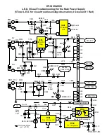

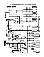
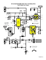

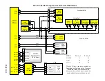
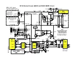

DP-3X POWER SUPPLY SHUT DOWN EXPLANATION
PAGE 01-09
On the Power PWB
•
SW –7V Voltage Loss Detection
Monitored by
D949
and routed through
D950
. In this circuit, if the
SW –7V
is
lost, the positive
+6.3V
will forward bias
D949
and it will fire causing shut down.
•
SW –28V Voltage Loss Detection
Monitored by
D952
and routed through
D953
. In this circuit, if the
SW –28V
is
lost, the positive
+28V
will forward bias
D952
and it will fire causing shut down.
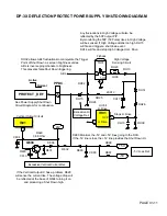
In the Deflection Circuit
•
–5V Voltage Loss Detection
Monitored by
DK90
. In this circuit, if the
–5V
is lost, the positive
+5V
will forward
bias
DK90.
Any abnormality seen in the deflection circuit will generate a high that will be routed through the
PPD4
connector pin
6
to
D951
.
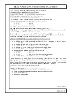
(See DP-3X Deflection Protect Shut-Down Circuit Diagram for details)
Voltage Too High Detection
All voltage too high detections circuits are active (Hi) and routed to the base of
Q904,
Common
Action Circuit.
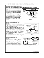
(See DP-3X Power Supply Shut-Down Circuit Diagram for details)
On the Power PWB.
•
SW +115V Voltage Too High Detection
Monitored by
D931
and routed through
D930
.
•
Audio Ground
If the Audio Output IC
IAA1
has an internal short, the Audio ground will go positive. This is Moni-
tored by
D960
and routed through
D961.
•
SW +10V Voltage Too High Detection
Monitored by
D957
and routed through
D958
.
•
SW +5.5V Voltage Too High Detection
Monitored by
D947
and routed through
D948
.
From, the Deflection circuit output called Protect_Def.
•
DH14 High Voltage Too High Sensing Circuit.
This circuit monitors the
High Voltage
line generated by rectify-
ing the pulse from the flyback
TH01
pin
5
. If the voltage at the cathode of
DH15
goes too high, this zener will fire.
This high will be routed to pin
6
of
PPD4
to
Protect_Def
. Any abnormality seen in the deflection circuit will gener-
ate a high that will be routed through the
PPD4
connector pin
6
to
D951
.
(See DP-3X Deflection Protect Shut-Down
Circuit Diagram for details)
•
At the same time, the zener diode
DH14
will fire and this high will be routed to pin
7
of
IH01
. This is the
Horizontal Drive for High Voltage and this IC will shut off, turning off High Voltage drive pulses.
Excessive Current Detection
(See DP-3X Power Supply Shut-Down Circuit Diagram for details)
On the Power PWB.
•
SW +115V Excessive Current Detection
Monitored by
Q905
and
D928
and routed through
D930.
If the Deflec-
tion/High Voltage Circuit draws too much current,
R927
will develop a larger voltage drop. This will cause the base
voltage of
Q905
to fall turning on this transistor. When this happens, it’s collector will go high. This high will be
routed to
D928
causing it to fire. This high will be routed through
D930
and to the base of
Q904
shutting off the
relay.
In the Deflection Circuit on the Power/Deflection PWB.
•
Q604 Vertical Circuit Excessive Current Sensing Circuit.
This circuit monitors the
+28V
line going to
I601
Ver-
tical Output IC. If the IC draws too much current,
R629
will develop a larger voltage drop. This will cause the base
voltage of
Q604
to fall turning on this transistor. When this happens, it’s collector will go high. This high will be
routed through
D608
and to pin
6
of
PPD4
to
Protect_Def
. Any abnormality seen in the deflection circuit will gen-
erate a high that will be routed through the
PPD4
connector pin
6
to
D951
.
(See DP-3X Deflection Protect Shut-
Down Circuit Diagram for details)
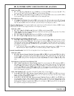
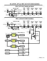
On the CRT PWB PROT_CPT.
(
See PROT_CPT & PROT_SW Shut Down Circuit Diagram).
•
On the RED CRT PWB +220V Excessive Current Detection
Monitored by
RE35
. If the
220V
draws too much
current, the base voltage of
QE08
will fall turning it on. The collector will go high. This high will go through
ERG1
pin
7
,
PSC
pin
3
,
PPS4
pin
6
to
D959
.
•
On the BLUE CRT PWB VM+220V Excessive Current Detection
Monitored by
REF1
. If the
VM220V
draws
too much current, the base voltage of
QEA8
will fall turning it on. The collector will go high. This high will go
through
EGB1
pin
8
,
PSC
pin
2
, to the base of
Q554
on the Signal PWB. This high turns on
Q554B and it’s col-
lector goes low. This low is routed to the PPS4
pin
5
to the cathode of
D944
causing D945 to fire and pull the
base of Q906 low turning it on causing shut down.
Содержание 46W500
Страница 2: ...DP 3X BLANK PAGE NOTES BLANK PAGE ...
Страница 6: ...DP 3X BLANK PAGE NOTES BLANK PAGE ...
Страница 7: ...DP 3X CHASSIS INFORMATION POWER SUPPLY INFORMATION SECTION 1 ...
Страница 8: ...DP 3X BLANK PAGE NOTES BLANK PAGE ...
Страница 23: ...DP 3X CHASSIS INFORMATION MICROPROCESSOR INFORMATION SECTION 2 ...
Страница 24: ...DP 3X BLANK PAGE NOTES BLANK PAGE ...
Страница 35: ...DP 3X CHASSIS INFORMATION VIDEO INFORMATION SECTION 3 ...
Страница 36: ...DP 3X BLANK PAGE NOTES BLANK PAGE ...
Страница 50: ...DP 3X BLANK PAGE NOTES BLANK PAGE ...
Страница 51: ...DP 3X CHASSIS INFORMATION AUDIO INFORMATION SECTION 4 ...
Страница 52: ...DP 3X BLANK PAGE NOTES BLANK PAGE ...
Страница 57: ...DP 3X CHASSIS INFORMATION DEFLECTION INFORMATION SECTION 5 ...
Страница 58: ...DP 3X BLANK PAGE NOTES BLANK PAGE ...
Страница 69: ...DP 3X CHASSIS INFORMATION DIGITAL CONVERGENCE INFORMATION SECTION 6 ...
Страница 70: ...DP 3X BLANK PAGE NOTES BLANK PAGE ...
Страница 83: ...DP 3X CHASSIS INFORMATION ADJUSTMENT INFORMATION SECTION 7 ...
Страница 84: ...DP 3X BLANK PAGE NOTES BLANK PAGE ...
Страница 98: ...DP 3X BLANK PAGE NOTES BLANK PAGE ...
Страница 99: ...DP 3X CHASSIS INFORMATION MISCELLANEOUS INFORMATION SECTION 8 ...
Страница 100: ...DP 3X BLANK PAGE NOTES BLANK PAGE ...
Страница 111: ...DP 3X CHASSIS INFORMATION DP 33W 46W500 DVD PLAYER TROUBLESHOOTING SECTION 9 ...
Страница 112: ...DP 3X BLANK PAGE NOTES BLANK PAGE ...
Страница 131: ...DP 3X CHASSIS INFORMATION THINGS YOU SHOULD KNOW SECTION 10 ...
Страница 132: ...DP 3X BLANK PAGE NOTES BLANK PAGE ...
Страница 134: ...DP 3X BLANK PAGE NOTES BLANK PAGE ...
Страница 161: ...DP 3X BLANK PAGE NOTES BLANK PAGE ...
Страница 162: ...DP 3X BLANK PAGE NOTES BLANK PAGE ...


