


The power point must be connected to a suitbale earth wiring, in conformity to current
safety regulations.
The colours of the wires in the built-in gas hob power cable may not correspond with the
colours marked on the terminals of your
electrical plug. The plug should in any case be wired as follows:
1.Connect the green/yellow wire to the terminal marked with the letter E or the earth
symbol or coloured green/yellow;
2.Connect the blue wire to the terminals marked with the letter N or cloured black;
3.Connect the brown wire to the terminal marked with the letter L or coloured red.
It is possible to connect the appliance directly to the mains supply by means of a heavey
duty switch with 3 mm minimum distance between contacts.
The power supply cord must not touch against any hot surfaces and must be placed so
that it’s temperature does not exceed 75
℃
at any point along its length.
After having installed the appliance, the power switch or power plug must always be in a
accessible position.
NOTE: for connections to the mains power supply, never use adapters, reductions
or multiple power points as there may overheat and catch fire.
In the event that installation should require modifications to the mains supply wiring system
or if the power plug is not suitable for the type
of power point available, it is recommended that a qualified technician be called to carry
out substitution.
The technician will also have to verify that the cross-section of the electric cables on the
power point match the appliance’s power rating.
●
●
●
●
●
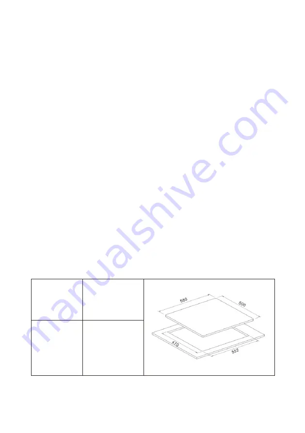
CUT-OUT DIMENSION
Model
HHU60GASS
552x470mm
CutOutDimension
(
L x W, mm
)
12
Содержание HHU60GASS
Страница 1: ...MODEL NO HHU60GASS...
Страница 17: ......


