3
No.
Indicator/Port
Description
8
Gigabit SFP
Fiber Optical
Port
Used for connection to another
device via an optical fiber when
plugged into with an optical module.
9
Reset Button
Used
for
restoring
all
the
configurations of the switch to the
default settings.
10
Power Supply
Use the attached power cord to
connect the switch to a socket.
11
Grounding
Terminal
Used
for
connecting
to
the
grounding cable to protect the
switch from lightning.
2
Installation
Please select the appropriate installation method according to the
actual needs.
Note
If screws are not provided in the package, prepare them yourself.
Before You Start
Ensure that the desktop, wall, rack, or rail is stable and firm
enough.
Keep the room well-ventilated. Leave at least 10 cm of heat
dissipation space around the device.
Keep at least 1.5 cm vertical distance between two adjacent
devices for rack-mounted installation.
2.1
Desktop Installation
Place the device on the desk.
2.2
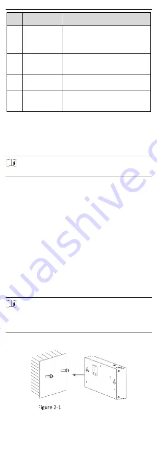
Wall-Mounted Installation
Steps
1.
Check the distance between the two hanging holes on the rear
cover of the device.
2.
Insert two M4 screws into the wall.
Note
●
Ensure that the distance between the two screws equals to the
distance between the two hanging holes.
●
Set aside at least 4 mm of the screw bodies outside the wall.
3.
Align the hanging holes with the screws, and hang the device on
the screws.
Wall-Mounted Installation


