background image

CameraLink Line Scan Camera

·

User Manual


69 

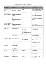
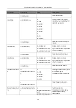
Parameter 

Command 

Value 

Description 

value and disable 
digital shift 

z: write serial port 
value and enable 
digital shift 

y=x × 511 /6 +511 

z=x × 511/6+66047 

shift is -6 to 6. 

Eg. w DigitalShift 512. It 
means setting gain as 0.01, 
and disabling digital shift. 

Eg. w DigitalShift 66048. It 
means setting gain as 0.01, 
and enabling digital shift. 

r DigitalShift 

When value is larger 
than 65536, digital 
shift is enabled. 

Read digital shift. 

If digital shift is enabled, read 
z and x =(z-66047) × 6/511. 

If digital shift is disabled, read 
y, and x=y × 6/511-6. 

BalanceWhiteAuto  w BalanceWhiteAuto 

0—off 

1—continue 

2—once 

Set white balance mode. Eg: 
w BalanceWhiteAuto 2. 

r BalanceWhiteAuto 

0—off 

1—continue 

2—once 

Read white balance mode. 

BlackLevel 

w BlackLevel x 

x: 0-4095 

Set black level. Eg. w 
BlackLevel 5. 

r BlackLevel 


Read black level. 

BlackLevelEnable 

w BlackLevelCtrl x 

x: 

0—disable 

1—enable 

Set black level enable. 

Eg. w BlackLevelCtrl 1. 

r BlackLevelCtrl 


Read black level enable. 

GammaAbsVal 

w GammaAbsVal 
x×100+y 

x: game value 
y: 
0x20000—represents 
sRgb 

0x10000—represents 
User 

Set Gama value, and 
GamaEnable on is availabe. 
Eg:   

w GammaAbsVal 2 × 100+0 × 
10000. 

r GammaAbsVal 


Read Gamma value. 

Содержание CameraLink

Страница 1: ...CameraLink Line Scan Camera User Manual ...

Страница 2: ...TY SATISFACTORY QUALITY OR FITNESS FOR A PARTICULAR PURPOSE THE USE OF THE PRODUCT BY YOU IS AT YOUR OWN RISK IN NO EVENT WILL HIKROBOT BE LIABLE TO YOU FOR ANY SPECIAL CONSEQUENTIAL INCIDENTAL OR INDIRECT DAMAGES INCLUDING AMONG OTHERS DAMAGES FOR LOSS OF BUSINESS PROFITS BUSINESS INTERRUPTION OR LOSS OF DATA CORRUPTION OF SYSTEMS OR LOSS OF DOCUMENTATION WHETHER BASED ON BREACH OF CONTRACT TORT ...

Страница 3: ...en tested and found to comply with the limits for a Class A digital device pursuant to part 15 of the FCC Rules These limits are designed to provide reasonable protection against harmful interference in a residential installation This equipment generates uses and can radiate radio frequency energy and if not installed and used in accordance with the instructions may cause harmful interference to r...

Страница 4: ... www recyclethis info 2006 66 EC battery directive This product contains a battery that cannot be disposed of as unsorted municipal waste in the European Union See the product documentation for specific battery information The battery is marked with this symbol which may include lettering to indicate cadmium Cd lead Pb or mercury Hg For proper recycling return the battery to your supplier or to a ...

Страница 5: ...duct may be damaged Avoid sudden collision and pack the product with the accompanied carton and cushioning material or similar package Using Environment In order to reduce the risk of fire or electric shock do not let the product get wet or damp Do not drop objects onto the product and avoid vigorous vibration Keep the product away from magnetic interference Do not use the product in extremely hea...

Страница 6: ...t when problems arise the product can be packed with packaging materials and sent to the agent or returned to the manufacturer for processing The company does not bear any liability for accidental damage during transportation caused by non original packaging This product is a precision electronic device no components can be maintained by user please do not disassemble the device arbitrarily Cleani...

Страница 7: ...CameraLink Line Scan Camera User Manual vii E mail tech_support hikrobotics com Website en hikrobotics com ...

Страница 8: ...era to MVS Client Software 9 Chapter 5 Quick Started with MVS 10 5 1 Client Software Layout 10 5 2 Set Parameters 11 5 3 Transport Layer Control 12 5 4 Serial Port Tool 13 Chapter 6 Image Acquisition 15 6 1 Set Line Rate 15 6 2 Set Trigger Mode 15 6 2 2 Set Free Trigger Mode 17 6 2 3 Set Line Trigger Mode 17 6 2 4 Set Frame Trigger Mode 19 6 2 5 Set Line Frame Trigger Mode 21 6 3 Set Trigger Sourc...

Страница 9: ...fferential Singal Source Outputs Differential Signal 41 8 2 2 Differential Signal Source as Single ended Signal 41 8 2 3 Single ended Signal Source Outputs Single ended Signal 41 Chapter 9 Image Parameter 43 9 1 View Resolution 43 9 2 Set ROI 43 9 3 Set Image Reverse 44 9 4 Set Pixel Format 44 9 5 Set Test Pattern 45 9 6 Set Exposure Time 47 9 7 Set Gain 48 9 7 1 Set Analog Gain 48 9 7 2 Set Digit...

Страница 10: ...can Camera User Manual x 10 2 TDI Function 56 10 3 Transport Layer Control 58 10 4 Save and Load User Set 58 10 5 Update Firmware 60 Chapter 11 Trouble Shooting 63 Chapter 12 Revision History 64 Appendix Command List 65 ...

Страница 11: ...with varied models Type I is 4K camera and type II is 8K camera For specific appearance and dimension please refer to the camera s specification for details The appearance is subject to change and the actual device you purchased shall prevail Figure 1 1 Appearance Type I Figure 1 2 Appearance Type II ...

Страница 12: ...camera you should use M3 screw 3 USB Interface It is used to update firmware 4 Screw hole for CL Interface It is used to fix CameraLink cable 5 CL1 Interface It refers to the CameraLink1 with SDR interface and it is used to transmit data and provide serial communication 6 CL2 Interface It refers to the CameraLink2 with SDR interface and it is used to transmit data 7 LED Indicator It indicates the ...

Страница 13: ...2 pin Power and I O Interface Table 2 1 Description No Signal I O Signal Source Description 1 GND Camera power supply ground 2 DC_PWR Camera power supply 3 IO_IN0_P Line 0 Differential input 0 4 IO_IN0_N Line 0 Differential input 0 5 GND Signal ground 6 IO_IN1_P Line 3 Differential input 1 7 IO_IN1_N Line 3 Differential input 1 8 Reserved 9 IO_OUT0_P Line 1 Differential output 0 10 IO_OUT0_N Line ...

Страница 14: ...ils Table 2 2 Indicator Status Description No Indicator Status Description 1 Very slow flashing red The data transmission exception occurs 2 Solid blue After starting up the camera shows this status No data is transmitting 3 Rapid flashing blue The camera is acquiring images in internal trigger mode 4 Slow flashing blue The camera is acquiring images in external trigger mode 5 Flashing blue and re...

Страница 15: ...e grabber interface 4 Lens 1 4K camera It refers to C mount M42 mount or other lens 8K camera It refers to F mount V mount or other lens You need to purchase lens separately 5 Frame Grabber 1 It refers to CameraLink frame grabber that you need to purchase separately 6 Lens Adapter 1 4K camera M42 is used for the lens mount of 4K camera and the camera is equipped with a lens adapter for C mount len...

Страница 16: ...or different frame grabbers their wirings may be different The principle is that the CameraLink1 CL1 interface and CameraLink2 CL2 interface of camera should connect to the first and second interface of frame grabber respectively Steps 1 Fix the camera to the installation position 2 Install the lens to the camera body 3 Connect the camera to CameraLink frame grabber via CameraLink cable 4 Connect ...

Страница 17: ...bber you purchased 4 2 Set Frame Grabber Software After installing the camera you are required to set frame grabber parameters via the frame grabber software Incorrect parameters or not setting parameters may make the camera fail to output images Here we take Dalsa and Matrox frame grabber as an example The parameter names may vary from different frame grabbers and are subject to the frame grabber...

Страница 18: ...are is used to connect the camera set its parameters etc The MVS client software is compatible with 32 64 bit Windows 7 10 operating systems Software version in this manual is V3 1 0 If other versions are used the graphic user interface may differ You can download Windows version client software from en hikrobotics com For other versions of client software please contact technical support personne...

Страница 19: ...ts 4 4 Connect Camera to MVS Client Software Steps 1 Click in Camera Link of device list to search the device The refresh process may take a few minutes please wait patiently 2 Right click the device and click Bauderates Setting to set baud rate according to actual demand 3 Double click the device or click to connect the device to the MVS client software ...

Страница 20: ... the client software please refer to the actual one you got Table 5 1 Description of the Main Window No Area Name Description 1 Menu Bar The menu bar includes File View Settings Tool and Help 2 Control Toolbar The control toolbar provides quick operations for the device 3 Device List Area The device list area displays the different devices to be connected 4 Interface and Device Information Area Th...

Страница 21: ... can view and set device s attributes 5 2 Set Parameters The camera setting supports 3 kinds of user level Beginner Expert or Guru which displays different camera attributes For Guru Level it provides the most comprehensive camera attributes for professional use Here we take Guru Level as an example Figure 5 2 Feature Tree Table 5 2 Attribute Description Attribute Description Device Control You ca...

Страница 22: ... control to convert source signal of external trigger into internal signal Frequency Converter Control You can set frequency converter control to convert external signal of different frequencies into internal signal Shading Correction You can set shading correction to correct shade Digital IO Control You can set the different input and output signals Transport Layer Control You can set the paramet...

Страница 23: ...fer to the specification of the camera for details 5 4 Serial Port Tool Apart from the MVS client software and frame grabber software the serial port tool can be used to detect camera status read and set its parameters You can set camera parameters by connecting CameraLink serial port cable When accessing the camera or using the terminal in the application software you are required to set the para...

Страница 24: ...ommand has been set the returned value is as follows Success r n If the reading command has been set the returned value is as follows Success r n r n get Note Name Value r n If setting the writing or reading command fails the returned value is as follows Failed r n r n Wrong input format r n Executing the reading or writing command is as follows Table 5 5 Command for Writing or Reading Command for...

Страница 25: ...is proportional to the line rate and is inversely proportional to the height of the image area that is Fps Lps Image Height In MVS client software click Acquisition Control Acquisition Line Rate Hz and enter Acquisition Line Rate Hz You can view real time line rate and frame rate in Resulting Line Rate Hz and Resulting Frame Rate Fps respectively Figure 6 1 Set Line Rate 6 2 Set Trigger Mode The c...

Страница 26: ...one line is exposed when a trigger signal is input Frame trigger mode Acquisition Control Trigger Selector and Trigger Mode Trigger Selector Frame Burst Start Trigger Mode On and Trigger Selector Line Start Trigger Mode Off After receiving frame trigger signal the camera will start to expose and generate image data The camera outputs images according to current line rate Line frame trigger mode Ac...

Страница 27: ...rameter In this mode the camera itself generates the trigger signal You can adjust the line rate parameter according to actual demand 6 2 3 Set Line Trigger Mode In this mode line trigger is on and frame trigger is off and the frequency of the external line trigger control signal determines the line rate Only one line is exposed when a trigger signal is input The principle of line trigger is shown...

Страница 28: ...ge of the trigger signal is valid that is camera exposure and acquisition at the beginning of the rising edge of the trigger signal and the whole process will stop when the camera acquires the line signal that is able to output a complete frame Falling Edge refers to the falling edge of the trigger signal is valid that is camera exposure and acquisition at the beginning of the falling edge of the ...

Страница 29: ... receives new frame trigger signal when it has not triggered specific line number and this new signal will be discarded The line rate and exposure time determines frame trigger time The less the exposure time and the higher the line rate the less the frame trigger time will be Steps 1 Click Acquisition Control Trigger Selector 2 Select Frame Burst Start as Trigger Selector and On as Trigger Mode F...

Страница 30: ...and acquisition at the beginning of the falling edge of the trigger signal and the whole process will stop when the camera acquires the line signal that is able to output a complete frame Level High refers to the level high of the trigger signal is valid The trigger is active as long as the trigger signal is high Level Low refers to the level low of the trigger signal is valid The trigger is activ...

Страница 31: ...rame Timeout Enable to enable this function In line frame trigger mode regarding to different conditions the camera has various processing mechanism as follows If the Frame Timeout function is disabled the line trigger signal will work only after the camera receives frame trigger signal When the outputted line number reaching specific frame height the camera outputs a frame image and then it no lo...

Страница 32: ...than or equal to the configured frame height register value Otherwise the camera cannot reach the frame rate you want Settings for line frame trigger mode are as follows Steps 1 Click Acquisition Control Trigger Selector 2 Select Frame Burst Start as Trigger Selector and On as Trigger Mode Figure 6 12 Set Frame Trigger Parameter 3 Select different frame trigger signals as Trigger Source according ...

Страница 33: ...trigger shaft encoder control frequency converter control and frame grabber trigger control Their principle and parameter are shown below Table 6 2 External Trigger Mode Principle and Parameter External Trigger Source Supported Trigger Mode Parameter Parameter Value Principle Software trigger Frame trigger Acquisition Control Trigger Source Software The software sends trigger signal to the camera ...

Страница 34: ... Line0 Line3 and encoder module out Frame grabber trigger control Frame trigger or line trigger Acquisition Control Trigger Source CC1 CC2 CC3 C C4 Frame grabber triggers camera to acquire images by sending signal via CameraLink cable These 5 trigger sources are valid only when the Trigger Mode is On For different models of cameras the specific parameters mentioned above may differ and the actual ...

Страница 35: ...Selector and On as Trigger Mode 3 Select Line 0 or Line 3 as Trigger Source Figure 6 17 Set Hardware Trigger 6 3 3 Set Shaft Encoder Control The camera has shaft encoder control module and it can receive the trigger from shaft encoder of A and B channels For example the output signal of shaft encoder control module can be used as the input signal of camera line trigger or frame trigger In line tri...

Страница 36: ...mple movement of camera Non uniform motion can also be a perfect match A trigger signal can be set as acquiring multiple lines or multiple frames with adjustable ratio This trigger source uses shaft encoder module to receive signal A and signal B with phase difference After internal computing of the module the outputted signal can be used as camera s trigger signal Click Encoder Control and set En...

Страница 37: ...emonstration When selecting Encoder Module Out as Trigger Source you can also set Encoder Trigger Mode including Any Direction and Forward Only Figure 6 21 Set Encoder Trigger Mode 6 3 4 Set Frequency Converter Control The camera has a frequency converter function which allows the frequency of the camera signal to be triggered different from the input signal frequency In frame trigger mode or line...

Страница 38: ...l is accepted Multiplier After the signal is processed by the PreDivider it is sent to the Multiplier The Multiplier multiplies the signal by an integer to increase its signal frequency and then the signal is sent to the PostDivider Parameter can be set as rising or falling edge If a rising edge is set each rising edge of the signal coming from the PreDivider will be locked to match the signal of ...

Страница 39: ...coder counter and trigger debouncer Different trigger modes can set various trigger parameters and their relation is shown below Table 6 3 Trigger Mode and Trigger Parameter Trigger Mode Trigger Parameter Software Trigger Hardware Trigger Shaft Encoder Control Frequency Converter Control Frame Grabber Trigger Burst Frame Count Support Support Not support Support Support Trigger Delay Support Suppo...

Страница 40: ... Trigger delay Trigger_in 3 Trigger delay Figure 6 25 Single Frame Mode Sequence Diagram Multiple Frame Mode In this mode the camera outputs multi frame images by receiving one trigger signal You can set the burst number by clicking Acquisition Control Acquisition Burst Frame Count and the range is from 1 to 1023 If Acquisition Burst Frame Count 1 it is single frame mode If Acquisition Burst Frame...

Страница 41: ...al The principle and parameter of trigger activation are shown below Table 6 4 Trigger Activation Principle and Parameter Trigger Activation Parameter Parameter Value Principle Rising edge Acquisition Control Trigger Activation Rising Edge Rising Edge refers to the rising edge of the trigger signal is valid that is camera exposure and acquisition at the beginning of the rising edge of the trigger ...

Страница 42: ...he trigger signal is low You can set trigger activation as shown below Steps 1 Click Acquisition Control Trigger Activation 2 Select Falling Edge Rising Edge Level High or Level Low as Trigger Activation Figure 6 29 Select Trigger Activation 6 4 4 Shaft Encoder Counter There are 2 types of encoder counter modes including Ignore Direction and Follow Direction The former one records data of all dire...

Страница 43: ...rigger Thus it is necessary to debounce the external trigger signal and its sequence diagram is shown below Before debounce After debounce Trigger_in1 Trigger_in2 Trigger_in3 Trigger_in2 Trigger_in3 Debouncer Time Debouncer Time Debouncer Time t1 t2 t3 t4 t5 t6 t1 t2 trigger signal is ignored t3 t4 trigger signal outputs after delaying t3 t5 t6 trigger signal outputs after delaying t5 Figure 6 31 ...

Страница 44: ...2 Set Line Debouncer Time When the configured debouncer time is larger than trigger signal time and the trigger signal will be ignored When the configured debouncer time is smaller than trigger signal time and the trigger signal will output after delaying ...

Страница 45: ... Selector and enable Strobe Enable Figure 7 1 Select Output Signal 7 2 Set Output Signal The output signal of the camera is level signal that is used to control external devices such as light source etc 7 2 1 Enable Level Inverter The level inverter function is used to control the camera s output signal manually You can click Digital IO Control and enable Level Inverter Figure 7 2 Enable Level Inv...

Страница 46: ... is used to directly output I O signal to external devices when camera s event source occurs You can enable strobe signal as shown below Click Digital IO Control set Exposure Start Active as Line Source and enable Strobe Enable The camera currently supports setting exposure start active as line source only Figure 7 3 Enable Strobe Signal ...

Страница 47: ... s ground signal with external ground signal if Line 0 and Line 3 adopt RS 422 standard 1 2 3 4 5 6 7 8 9 10 11 12 Input RS 422 or RS 644 Signal 12 Pin Interface Gnd External Gnd Gnd 3 3V 3 3V 10KΩ 8 2KΩ Gnd To Fpga 120Ω Receiver I O In I O In Camera Figure 8 1 Inputting RS 422 or RS 644 Signal RS 422 standard defines the connection of the bus structure and the inputs of several cameras can be con...

Страница 48: ...s input terminal adopts RS 644 standard signal the input terminal must enable 120 Ω terminal resistance LVTTL Standard Input If the camera s input terminal adopts LVTTL standard signal the input terminal s 120 Ω terminal resistance must be disabled and its input electrical feature requirement is shown below Table 8 1 Electrical Feature Requirement of LVTTL Voltage Description 0 V to 5 0 V It is a ...

Страница 49: ...onnects the camera via 12 pin power and I O cable The RS 422 standard RS 644 standard and LVTTL standard is applied to this output signal RS 422 Standard Output In order to make sure the normal operation of output circuit it is required to connect camera s ground signal with external ground signal The output interface can be connected to the RS 422 bus structure as a master dispenser 1 2 3 4 5 6 7...

Страница 50: ...ard output it is required to add a resistance network in camera s output location In order to make sure the normal operation of output circuit it is required to connect camera s ground signal with external ground signal Figure 8 5 Outputting RS 644 Signal LVTTL Standard Output When adopting LVTTL standard as the output signal the wiring is shown below Figure 8 6 Outputting LVTTL Signal ...

Страница 51: ... or Input 1 Negative Line3 Signal Source GND Figure 8 7 5 V Differential Signal Source Outputs Differential Signal 8 2 2 Differential Signal Source as Single ended Signal The specific wirings of 5 V and 12 V differential signal sources outputting single ended signal are shown below OUT A Input 0 Positive Line0 or Input 1 Positive Line3 OUT Ã Differential Signal Source Camera Power Signal Source Po...

Страница 52: ... 1 Positive Line3 Single ended Signal Source Camera Power Signal Source Power PWR VCC Camera Power Ground Camera GND Input 0 Negative Line0 or Input 1 Negative Line3 Signal Source GND Signal Ground Hang Figure 8 9 5 V and 12 V Single ended Signal Sources Output Single ended Signal ...

Страница 53: ... only interested in a certain region of the image you can set a Region of Interest ROI for the camera Setting Region of Interest can reduce the bandwidth of the image being transmitted Thus increasing the frame rate to some extent The camera currently supports 1 ROI only that is there is Region 0 for Region Selector parameter only Region of interest can be set only when you stop real time acquisit...

Страница 54: ...ontrol and enable Reverse X according to actual demands Figure 9 3 Set Image Reverse For different models of cameras the image reverse function may differ and the actual product you purchased shall prevail 9 4 Set Pixel Format The camera supports many pixel formats For specific pixel formats that the camera supports please refer to the specifications of the camera ...

Страница 55: ...top real time acquisition For different models of cameras the specific pixel format may differ and the actual product you purchased shall prevail 9 5 Set Test Pattern The camera supports test pattern function When there is exception in real time image you can check whether image of test mode have similar problem to determine the reason This function is disabled by default and at this point the out...

Страница 56: ...g Mono Bar Checkboard Oblique Mono Bar and Vertical Color Bar For color camera it also supports Gradual Mono Bar and Horizontal Color Bar Here we take 4K camera for an example Figure 9 6 Mono Bar Test Pattern 4K Camera Figure 9 7 Checkboard Test Pattern 4K Camera Figure 9 8 Oblique Mono Bar Test Pattern 4K Camera Figure 9 9 Gradual Mono Bar Test Pattern 4K Camera Figure 9 10 Vertical Color Bar Tes...

Страница 57: ...tion Exposure Auto Description Off The camera does not expose automatically Once Adjust the exposure time automatically according to the image brightness After adjusting it will switch to Off Mode Continuous Adjust the exposure time continuously according to the image brightness You can set exposure time under Off mode as shown below Click Acquisition Control Exposure Time and enter Exposure Time ...

Страница 58: ...xample to set analog gain Click Analog Control Preamp Gain and select Preamp Gain according to actual demands Figure 9 14 Set Analog Gain For different models of the camera the analog gain range and setting method may be different please refer to the actual one you got When increasing the analog gain the image noise will increase too which will influence image quality If you want to increase image...

Страница 59: ...ncrease too which will severely influence image quality It is recommended to use analog gain first and then to adjust digital gain if the analog gain cannot meet demands 9 8 Set White Balance White balance is only available for color cameras White balance is the white rendition function of the color camera used to adjust the color temperature according to the environment The white balance refers t...

Страница 60: ...Analog Control Balance White Auto 2 Select Off Once or Continuous as Balance White Auto 3 Set AWB Color Temperature Mode 4 Set Balance Ratio Selector and Balance Ratio according to actual demands Figure 9 16 Set White Balance Balance Ratio Selector and Balance Ratio will be invalid when selecting Once or Continuous as Balance White Auto 9 9 Set Gamma Correction The camera supports Gamma correction...

Страница 61: ...enter Gamma according to actual demands Figure 9 18 Set Gamma Correction 9 10 Set Color Transformation Control Color transformation control is only available for color cameras The color transformation control function is designed to restore color and eliminate the overlap in the color channels Click Color Transformation Control enable Color Transformation Enable and set Color Transformation Value ...

Страница 62: ...ntrol Hue Enable enable Hue Enable enter Hue according to actual demands and its range is from 0 to 255 Figure 9 20 Set Hue Saturation Adjusting the saturation changes the colorfulness of the colors A higher saturation for example makes colors easier to distinguish Click Color Transformation Control Saturation Enable enable Saturation Enable enter Saturation according to actual demands and its ran...

Страница 63: ...he great difference of regional brightness You can also select rectangle region and the camera will adjust the region s exposure and white balance to achieve the best image quality Steps 1 Click Analog Control Auto Function AOI Selector 2 Select AOI 1 as Auto Function AOI Selector and set Auto Function AOI Width and Auto Function AOI Height according to actual demands Figure 9 22 Set AOI For diffe...

Страница 64: ... Non Uniformity Correction function that eliminates vertical line on the images You can set it as shown below Steps 1 Click Shading Correction 2 Select PRNUC Correction as Shading Selector 3 Click Execute of Activate Shading 4 Enable PRNUC Enable to enable correction function Figure 9 24 Set Shading Correction You can also enable PRNUC Target Enable to enable PRNUC target correction and set PRNUC ...

Страница 65: ...ce Family Name Read only It is the device series name Device Version Read only It is the device version Device Firmware Version Read only It is the device firmware version Device Serial Number Read only It is the device serial number Device User ID Read and write Device name and it is empty by default You can set according to your preference If Device User ID is empty the client software displays ...

Страница 66: ...ffer and the actual product you purchased shall prevail Currently only the 8K camera supports TDI function When switching TDI Mode the camera may have short period 3 s to 5 s of image exception which is a normal phenomenon TDI refers to Time Delay Integration and it is a method of line scanning which provides dramatically increased responsivity compared to other video scanning methods It permits m...

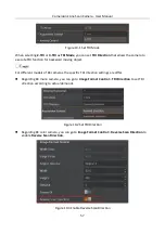
Страница 67: ...g object For different models of 8K cameras the specific TDI direction settings are differ Regarding 8K mono camera you can go to Image Format Control TDI Direction to set TDI direction according to actual demands Figure 10 2 Set TDI Direction Regarding 8K color camera you can go to Image Format Control Reverse Scan Direction to enable Reverse Scan Direction Figure 10 3 Enable Reverse Scan Directi...

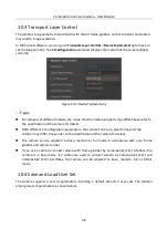
Страница 68: ...ion of the camera for details With different CI Configuration parameters the camera s line rate pixel format and tap number may differ Pease refer to the specification of the camera for details The camera can be adjusted to base medium or full mode in accordance with your frame grabber and camera model If you use 1 cable to connect camera with frame grabber by CameraLink1 CL1 interface the camera ...

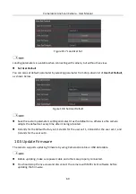
Страница 69: ... shown below Save Parameters Steps 1 Click User Set Control and select a user set in User Set Selector Here we take selecting User Set 1 as an example 2 Click Execute in User Set Save to save parameters Figure 10 6 Save User Set Load Parameters Steps 1 Click User Set Control and select a user set in User Set Selector Here we take selecting User Set 1 as an example 2 Click Execute in User Set Load ...

Страница 70: ...ters setting and select it as the default one otherwise the camera adopts the default set every time after it being rebooted 0 stands for the default factory set 1 stands for the user set 1 2 stands for the user set 2 and 3 stands for the user set 3 10 5 Update Firmware The camera supports updating firmware by using CameraLink cable or USB data cable Before updating make sure power cable and other...

Страница 71: ...e in the local computer 4 Click Update Figure 10 9 Update Firmware via CameraLink Cable Update Firmware via USB Data Cable The USB data cable you use should have data transmission function If the USB data cable cannot transmit data the PC will not find the disk Do not power off the camera during firmware updating Steps 1 Power on the camera and connect the camera to the PC via USB data cable 2 Cop...

Страница 72: ...CameraLink Line Scan Camera User Manual 62 Figure 10 10 Update Firmware via USB Data Cable ...

Страница 73: ... grabber software 2 Camera is in trigger mode 1 Check whether parameter settings of frame grabber software are set correctly 2 Disable trigger mode 3 Live view is black Aperture is closed Open the aperture 4 Live view is normal but camera cannot be triggered Incorrect I O wiring or trigger mode is not enabled 1 Check whether the I O wiring is correct under corresponding triggering mode 2 Check whe...

Страница 74: ...ment No Date Revision Details V2 0 1 UD17814B Dec 25 2019 Modify section Quick Started with MVS Add section Set Color Transformation Control Add section Set Hue and Saturation Modify section Set Shading Correction Add section TDI Function Modify section Update Firmware V1 0 0 UD14413B April 23 2019 Original version ...

Страница 75: ... Height Value Set the height Eg w Height 2000 r Height Read the height Reverse X w ReverseX x x 0 disable 1 enable Set image reverse X Eg w ReverseX 1 r ReverseX Read image reverse X Reverse Scan Direction w ReverseScanDirection x x 0 forward direction 1 reverse direction Set scan direction Eg w ReverseScanDirection 1 r ReverseScanDirection Read scan direction PixelFormat w PixelFormat x x 0x10800...

Страница 76: ...1073841824 it means setting line rate as 100000 and enabling line rate Eg w AcquisitionLineRate 100000 it means setting line rate as 100000 and disabling line rate r AcquisitionLineRate When value is larger than 10737441824 line rate is enabled Read line rate If line rate is enabled you reading and writing x are available and line rate is y x 1073741824 If line rate is disabled the reading value i...

Страница 77: ...erActivation 6 0 Rising edge 1 Falling edge Set rising trigger edge Eg w TriggerActivation 6 0 r TriggerActivation 6 0 Rising edge 1 Falling edge Read trigger edge setting TriggerDelay w TriggerDelayAbsVal 6 Value Set trigger delay Eg w TriggerDelay 6 100 r TriggerDelayAbsVal 6 Read trigger delay time TriggerSoftware w TriggerSoftware 6 Software trigger once Eg w TriggerSoftware 6 ExposureAuto w E...

Страница 78: ...o exposure upper limit Eg w AutoExposureTimeUpperLimi t 100 r AutoExposureTimeUpp erLimit Read auto exposure upper limit FrameTimeoutTim e w FrameTimeoutTime x x 33 10000 Set frame timeout time Eg w FrameTimeoutTime 34 r FrameTimeoutTime Read frame timeout time FrameTimeoutEna ble w FrameTimeoutEnable x x 0 disable 1 enable Set frame timeout enable Eg w FrameTimeoutEnable 0 r FrameTimeoutEnable Re...

Страница 79: ... z and x z 66047 6 511 If digital shift is disabled read y and x y 6 511 6 BalanceWhiteAuto w BalanceWhiteAuto 0 off 1 continue 2 once Set white balance mode Eg w BalanceWhiteAuto 2 r BalanceWhiteAuto 0 off 1 continue 2 once Read white balance mode BlackLevel w BlackLevel x x 0 4095 Set black level Eg w BlackLevel 5 r BlackLevel Read black level BlackLevelEnable w BlackLevelCtrl x x 0 disable 1 en...

Страница 80: ...ourceB x x 0 Line0 3 Line3 Set encoder source B Eg w EncoderSourceB 0 r EncoderSourceB Read encoder source B Encoder Trigger Mode w EncoderTriggerMode x x 0 AnyDirection 1 ForwardOnly Set encoder trigger mode Eg w EncoderTriggerMode 1 r EncoderTriggerMode Read encoder trigger mode Encoder Counter Mode w EncoderCounterMode x x 0 IgnoreDirection 1 FollowDirection Set encoder counter mode Eg w Encode...

Страница 81: ... rReset x x 1 Reset encoder reverse counter Eg w EncoderReverseCounterRese t 1 Input Source w InputSource x x 0 Line0 3 Line3 7 EncoderModuleOu t Set input source Eg w InputSource 7 r InputSource Read input source Signal Alignment w SignalAlignment x x 0 RisingEdge 1 FallingEdge Set signal alignment Eg w SignalAlignment 1 r SignalAlignment Read signal alignment PreDivider w PreDivider x x 1 128 Se...

Страница 82: ... w LineInverter 2 enable Line1 s inverter r LineInverter Read LineInverter status LineStrobe w LineStrobe 0 disable all 2 enable Line1 only 8 enable Line4 only Enable Line1 or Line4 Eg w LineInverter 2 enable Line1 s inverter r LineStrobe Read LineStrobe status LineDebouncerTim e w LineDebouncerTime x y x 5 CC1 0 Line0 3 Line3 y value Set trigger debouncer input is available Eg w LineDebouncerTime...

Страница 83: ...Selector w UserSetSelector x x 0 default 1 userset1 2 userset2 3 userset3 Set selected user parameter Eg w UserSetSelector 2 r UserSetSelector x 0 default 1 userset1 2 userset2 3 userset3 Read selected user parameter UserSetLoad w UserSetLoad 1 Execute Load UserSetDefault parameter UserSetSave w UserSetSave 1 Execute Save parameters setting to UserSetSelector UserSetDefaultSele ctor w UserSetDefau...

Страница 84: ...CameraLink Line Scan Camera User Manual 74 ...

Страница 85: ...UD17814B ...

Отзывы: