CameraLink Line Scan Camera
·
User Manual
2
Table 1-1
Appearance
No.
Interface
Description
1
Lens Mount
It is used to install lens. For specific lens mount, please refer
to the camera's specification for details.
2
Screw Hole
It is used to fix the camera to the installation position.
●
For type I camera, you should use M4 screw.
●
For type II camera, you should use M3 screw.
3
USB Interface
It is used to update firmware.
4
Screw hole for CL
Interface
It is used to fix CameraLink cable.
5
CL1 Interface
It refers to the CameraLink1 with SDR interface, and it is used
to transmit data and provide serial communication.
6
CL2 Interface
It refers to the CameraLink2 with SDR interface, and it is used
to transmit data.
7
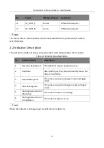
LED Indicator
It indicates the camera's status.
8
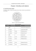
12-Pin Power and I/O
Interface
It refers to the 12-pin Hirose connector that provides power,
input/output signal, etc.
Содержание CameraLink
Страница 1: ...CameraLink Line Scan Camera User Manual ...
Страница 72: ...CameraLink Line Scan Camera User Manual 62 Figure 10 10 Update Firmware via USB Data Cable ...
Страница 84: ...CameraLink Line Scan Camera User Manual 74 ...
Страница 85: ...UD17814B ...


