


Operating Manual
Page 3
4.1. Installation Instructions ......................................................................................... 16
4.2. Wall Mounting ...................................................................................................... 16
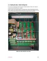
4.3. Control Cabinet Installation ................................................................................... 16
4.4. Dimensions, E-CO Lineguard 97 Controller & Wall Mounting Holes ........................ 17
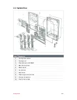
4.5. Base Board (Main Mother Board) .......................................................................... 17
4.5.1. Terminal Connection Diagram ................................................................... 17
4.5.2. Electrical Connections ............................................................................... 18
4.5.2.1. Main Power Supply ....................................................................... 18
4.5.2.2. Relay Outputs ............................................................................... 18
4.5.2.3. Current Outputs ............................................................................ 18
4.5.2.4. Serial Output ................................................................................. 18
4.6. 1739319 LG97 Relay Output Module ..................................................................... 18
4.6.1. Relay Module Outputs ............................................................................... 19
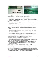
4.7. Sensor Information and Connections ..................................................................... 19
4.7.1. Sensor Immersion Installation Requirements ............................................. 20
4.8. Start up ................................................................................................................. 20
4.8.1. Typical Start-Up for measurement type ..................................................... 21
4.8.2. Configuration ............................................................................................ 21
4.8.3. Configuration Error.................................................................................... 21
4.8.4. Configuration Menu .................................................................................. 22
4.8.5. Initiation.................................................................................................... 22
4.8.6. Measurement Screen ................................................................................ 22
5. Operation ............................................................................................................ 23
5.1. General notes for Operation ................................................................................. 23
5.2. Operating Flow Chart ............................................................................................ 23
5.3. Operating Level ..................................................................................................... 24
5.4. Main Menu ........................................................................................................... 24
5.5. Settings ................................................................................................................. 24
5.5.1. Main Menu................................................................................................ 24
5.5.2. Measurement Parameter Settings ............................................................. 24
5.5.3. Controller Parameter Settings ................................................................... 24
5.5.4. Calibration................................................................................................. 24
5.6. Configuration ........................................................................................................ 25
5.6.1. Configuration System PAGE 1 .................................................................... 25
5.6.2. Configuration System PAGE 2 .................................................................... 25


