


Operating Manual
Page 18
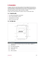
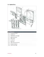
4.5.2. Electrical Connections
4.5.2.1. Main Power Supply
Utility: 120 VAC 60 Hz, 1 phase
L1 – Line
N – Neutral
PE - Ground
4.5.2.2. Relay Outputs
Relay No. Signal Description
Terminal Position Contact type
1
Alarm output
1 & 2
Normally Open
1 & 2a
Normally Closed
2
Measurement (Control) Module 1
(Switching Point 1)
3 & 4
Normally Open
3 & 4a
Normally Closed
3
Measurement (Control) Module 1
(Switching Point 2)
5 & 6
Normally Open
5 & 6a
Normally Closed
All E-CO Lineguard 97 Controller relay contacts are potential-free contacts. If relay
outputs are also needed for measurement (control) modules 2 and 3, an additional relay
module must be installed (See Section 4.6).
4.5.2.3. Current Outputs
Module
No
Signal Description
Terminal Position
1
Measurement (control) Module 1
7 & 8
2
Measurement (control) Module 2
9 & 10
3
Measurement (control) Module 3
11 & 12
When Connecting the power outputs, pay careful attention to the correct polarity and the
maximum load (600 ).
4.5.2.4. Serial Output
This port is for Henkel use only. NO access is currently available.
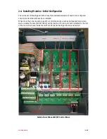
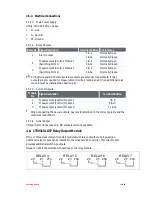
4.6. 1739319 LG97 Relay Output Module
If two or three measurement (control) modules with relay outputs are being used, an
additional relay module can be installed in the Lineguard 97 Controller. This relay module
provides additional switching outputs.
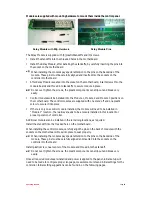
Image to right is the electrical connections to the relay module.
20
21
21a
RELAY 4
22
23
23a
RELAY 5
24
25
25a
RELAY 6
26
27
27a
RELAY 7


